COMP 310 |
Use Case-driven System Block Diagrams |
|
|
For information on Use Cases, see the Java Resources page on Use Cases.
("System block diagram" is the the more hardware-oriented term which emphasizes functionalities and intercommunications. For software engineering, some will call this sort of diagram a "software block diagram" or simply a "block diagram".)
A system block diagram is a high level modularization of the system that separates the overall system into maximally decoupled sub-systems. System block diagrams enable one to visualize the system as large interacting components that can be conceptualized and developed independently. This type of architecture also lends itself to greater flexibility and extensibility of the system, enabling it to grow and evolve more easily to adjust for changing requirements and demands. Creating a system block diagram early in the development process is critical for assembling teams of develops that can work in parallel on the project.
A system block diagram displays the high-level view of the encapsulated functional modules that compose a system. A system block diagram may show multiple layers of encapsulation, though internal layers are often relegated to separate diagrams for clarity's sake. In terms of system design, the modules in the system block diagram should exhibit maximal decoupling from each other.
System block diagrams help the developers understand the the parts fit into the larger whole. They are also very useful in helping maintain the proper level of decoupling in the system because excessive crossing of module boundaries will result in a "spaghetti diagram".
A system block diagram minimally consists of the following information:
The key to creating an effective system block diagram is the clear and complete articulation of the decoupled processes that compose the system. -- You cannot develop your system if you do not completely understand the functional modules of which it is comprised.
System Block Diagram References:
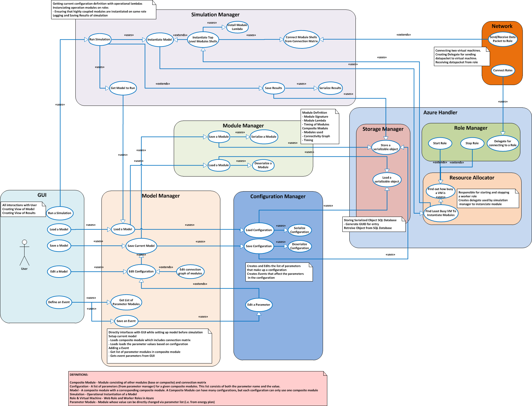
One of the best ways to generate a system block diagram is to approach it from use cases. By grouping use cases together, the functional modules of the system will emerge. Excessive coupling can easily be identified in the resulting diagram and the use cases and associated modules can then be modified to be more streamlined.
(Note: the following diagrams show solid lines with solid arrowheads to indicate that one use case "uses" another use case. Technically, those lines should be dotted lines with solid arrowheads as per the UML standard.)
Notice how the use cases have been organized into the system block diagram. (This diagram is the original diagram for a class project, made by the students who used the wrong arrowheads in the drawing. The closed arrowheads shown should in fact all be open arrowheads.)
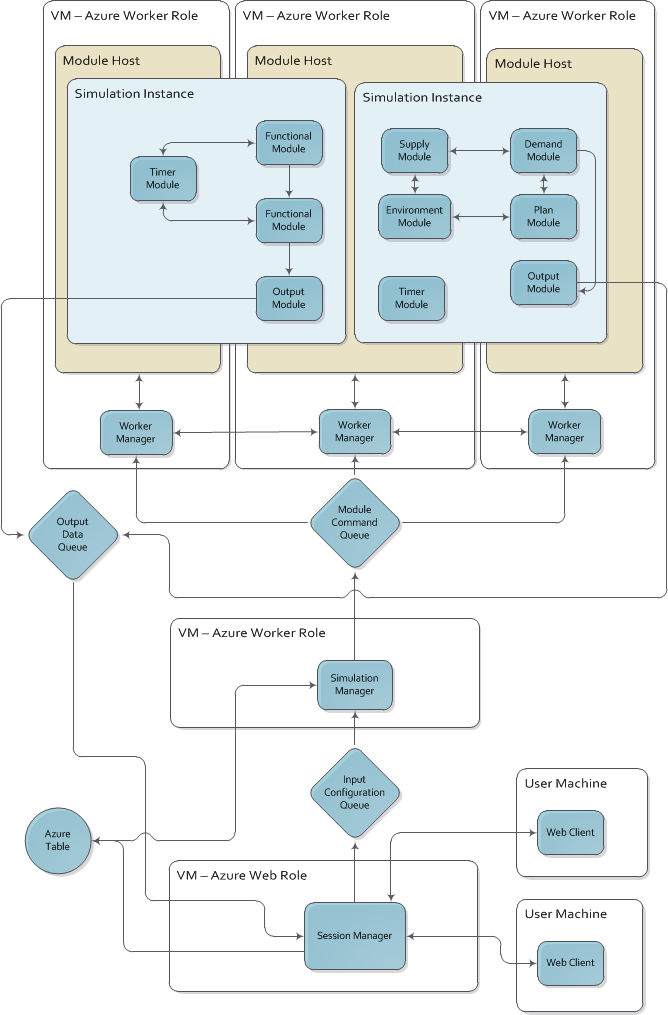
Note lack of critical details. (Once again, this is the original diagram for a class project where the students used the arrowheads that are not clearly the open arrowheads as they should be.)
© 2017 by Stephen Wong