StructureBuilder
StructureBuilder (SB) is a tool to create UML class diagrams and automatically
generate Java "stub codes". SB can also reverse engineer Java source/byte
code to produce the corresponding UML diagrams.
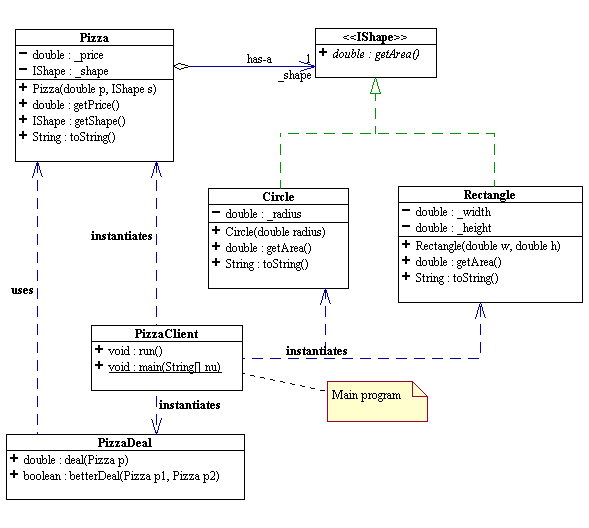
In this lab, we will use SB to design a Pizza program. Perform the following
steps to create the UML diagrams shown below. SB will generate code that
reflects the class structure, but not the specific actions on any objects.
For that, after using SB, you'll edit the resulting stub code to add the rest
of the code, filling in what each method should do.
-
Create a subdirectory called lab03 on your U: drive.
Somewhere on your Windows Program menu is the menu
item for WebGain StructureBuilder. Click on it to start SB.
-
Prepare to start a completely new diagram:
- In the File menu, choose Close All, to start your design from scratch.
- In the Tools menu, choose Preferences, and set the Default Source
Directory to your lab directory (i.e. lab03).
This is where all the generated files will be saved. While you are in
preferences, set the following as well:
- Class Diagrams:
- Icon Theme = UML
- When Dragging Line = Move
- Class Diagrams/Defaults
- Display Variable and Method Types = checked
- Show Method Parameters = checked
- CodeGen
- Generate Code Markers = unchecked
- Starting Curly ({) On New Line = unchecked
- In the File menu, select New/Project. A
Project dialog will pop up prompting you to enter a project name and
select the desired Input and Output directories. Enter PizzaLab
for the project name. Check to make sure that the Input and Output
directories are set to the Default Source Directory done in step 2.ii
above.
- In the File menu, select Save All. A file dialog will pop up, enter
a file name called Pizza and save it IN THE SAME DIRECTORY AS THE Default
Source Directory.
- In the File menu, choose New/Class Diagram, or equivalently, click
on the "New Class Diagram" button. In the resulting dialog box,
enter a name like "Pizza" for this diagram. Also, check the "Display
Variables and Method Types" and the "Show Method Parameters" boxes.
Then click on "OK".
You should see a new "Pizza" tab. Click on it.
- Now, make the diagram:
-
In the File menu, choose New/Class, or equivalently, click on the
"New Class" button. In the left pane, a new class box should appear.
In the right pane, some Java code to declare the new class should appear.
Both will use a default class name (e.g.,
Class_0).
We need to edit this new class. Double-click on the class diagram,
or equivalently, right-click and choose Properties, and a Properties
Dialog should appear.
- Select the Classes tab. Change the class name (in the Name textbox)
to
Circle. Make sure the Directory text box displays
the correct directory.
- Select the Variables tab. Add the radius field by clicking on the
New button Variables list box. By default, you will get
int
            newVariable
. Select (highlight) the int text and
type over double. Select the newVariable
text, and type over _radius. Make sure the "private"
radio button is selected.
-
Repeat the same process to create a class called
Rectangle
with width and height fields of type double.
You may want to keep the Properties dialog open. Note that you can
switch classes and create new classes from its interface also.
-
Create an interface called
IShape.
- In the File menu, choose New/Interface, or equivalently, click
on the "New Interface" button, which is located immediately to
the right of the New Class button. In the left pane, a new class
box should appear. Rename the interface as IShape.
- To add an (abstract) method for computing the area, select the
Methods tab. In the Methods list box, click the New button. By default
you will get the method
void newMethodName. Change
this to double getArea. Check the "abstract" check
box and the "public" radio button. NOTE: Though interface methods
are by definition public and abstract, we want to explicitly declare
them public and abstract in order for SB to display them correctly
The UML class diagram for IShape should display the getArea()
method in italic. In UML, all abstract methods are italicized.
- Make Circle and Rectangle implement IShape by dragging the
inheritance arrow (the middle one) from each subclass to IShape. You
may need to drag the classes around for a more readable placement.
- Generate method stubs for Circle and Rectangle by right-clicking each
inheritance arrow, and selecting Generate Method Stubs. Circle
and Rectangle should now each have a default stub code for the getArea()
method.
- Add a class called Pizza.
- Add a price field of type double. While that new field is selected,
check the Create Get Routine box. That creates a method get_price
returning that field. Rename get_price to getPrice.
- To make Pizza reference an IShape, select class Pizza.
In the lower far-right corner of the Pizza class diagram is an "association"
symbol. Click on it and drag it to the IShape class diagram.
- A field (i.e. variable) called iShape is automatically generated.
Rename the field to _shape.
- Create a Get Routine for _shape. Rename get_shape to getShape.
- Double-click on the link arrow, and check the aggregation check
box. Aggregation simply means "has-a". You can add the text
"has-a" to the link label and "_shape" to the
Role A text box. These texts are like comments and have no
effect on the code.
- Constructors are special pieces of code used to initialize
an instance of a class when it comes into existence.
- To add a constructor for Pizza, select the Methods tab of its Properties,
and select New/Constructor. In the Parameters area, add two new parameters:
double price and IShape _shape.
- Add a Circle constructor with parameter double radius.
- Add a Rectangle constructor with parameters double width and double
height.
Of course, you can also create constructors when you originally create
classes.
- Add a class called PizzaDeal with two methods.
- double deal(Pizza p)
- boolean betterDeal(Pizza p1, Pizza p2)
To add a new method to a class:
- select the Methods tab in the Properties Dialog.
- In the Methods list box, select New/User Method. By default you
will get the method
void newMethodName
- Change the return type and the method name accordingly.
To add a parameter to a method:
- select the desired method.
- in the Parameters tab, click the New button. A default int
newParam is created. Rename the type and the name accordingly.
- Reverse Engineering: Download
the class callled
PizzaClient to
your current lab directory. This is the main program which will make use of Pizza, PizzaDeal,
Circle, and Rectangle to figure out the better deal
between two pizzas. In the File menu, select Open. A
fiel dialog will appear. Choose the file type to be *.java and
select PizzaClient.java. The UML class diagram for PIzzaClient
should appear in the class diagram window.
- Add "dependencies" between different classes by dragging the dependency
arrow icon (just left of the association icon) to another class. In
this example, PizzaClient "depends" on Pizza, PizzaDeal, Circle, and
Rectangle. You can enter a label for a dependency arrow by double-clicking
on it and, filling out the pop-up dialog box. Dependency arrows
have no effect on code generation.
- Feel free to make modifications on your diagram. You can drag your
class diagrams around and bend the arrows in many different ways. You
just have to experiment with the tool.
- In the File menu, select Save All, and use the file name Pizza. This
should create the files PizzaClient.java, PizzaDeal.java,
Pizza.java, IShape.java, Circle.java,
and Rectangle.java in the specified directory.
-
Now define what this program actually does, i.e., define the methods described
by your diagram. Use DrJava (or your favorite
editor) to add the
methods to the corresponding class .java file.
Click here for the code of
PizzaDeal. Remember that
the IShape getArea method is abstract and so has no code
body. Make sure you add comments to the code as shown in the sample
code. The comments are written in "javadoc" style.
-
If you set up SB properly, you should be able to generate javadoc and
UML diagrams for your code in one click of a button: go to the menu Tools/Generate
Documentation; select private access type to generate javadoc for all fields
and methods, select the class diagrams you want to javadoc, and click the
Generate button! You can submit the generated UML diagrams and javadoc
html files as the official javdoc documentation of your work. You
will not need to export the diagrams to any files at all.
More information on running StructureBuilder
can be found here.
Koch Curve
This tutorial will lead you through the process of modeling the Koch curves
through a series of questions. By answering these questions, you will
have come up with appropriate design patterns to model the Koch curves and complete
a major portion of milestone 1 for the Koch Curve
programming assignment It is vital that you familiarize yourself with the
general
discussion of Koch curves before embarking on this process.
Koch Curve States
- A Koch curve is defined between two points. The figure above
represents the simplest of Koch curves.
- What should a Koch curve have as fields?
- What is the simplest constructor a Koch curve should then have?
- Let K be the initial straight line segment Koch curve in the above
figure. Now, click the Next Iteration button once. Note that K
now contains a bunch of Koch curves.
- How many Koch curves does K now have?
- What kind of Koch curves are those inside of K?
- Now, click the Next Iteration button once again.
- How many Koch curves does K now have?
- What kind of Koch curves are those inside of K?
- How many Koch curves does each of them have?
- And what kind of Koch curves are those? (Those that are inside of
those that are inside of K!)
- Has the behavior of K fundamentally changed from that in step 2?
- Now, click the Next Iteration button once again.
- How many Koch curves does K now have?
- What kind of Koch curves are those inside of K?
- Has the behavior of K fundamentally changed from that in step 3?
- Let's re-examine the behavior of K. In the beginning, K appears as a
straight line segment. When we click on the Next Iteration button
(step 2), we are basically "asking" K to "grow." K
responds by "changing" itself into something that contains N Koch
curves. When we ask K to grow again (step 3), K responds by asking
each of the N Koch curves it contains to grow! The result is that K
appears to have changed shape. In step 4 when we ask K to grow, K
responds in exactly the same way as in step 3: it asks its N Koch curves to
grow. K has stopped changing its "grow" behavior. Only
its shape appears to have changed. What we have here is the classic
phenomenon of "dynamic re-classification": a object appears to
have changed its behavior dynamically at run-time as if it has changed
classes. In fact, what happens is the object actually has states,
behaves differently in different states, and internally changes its state at
run-time.
- What design patterns can we use to model the behavior of Koch curves?
- How many states does a Koch curve have?
- The snow flake Koch curve is a Koch curve whose initial state consists of
a set of Koch curves in their initial states.
- What class/interface can we use to represent a set of Koch curves?
- What Koch curve constructor do we need in order to create snow flake
Koch curves?
Koch Curve Abstract Factory
We see from the above discussion that a Koch curve can grow from a
"basic" state to a "composite" state where it contains N
Koch curves in their own "basic" states. To endow the
Koch curve the capability of growing different kinds of Koch curves dynamically
at each growth step, we relegate the task of manufacturing Koch curves to an
abstract factory similar to the one for the
immutable list structure IList. Such an abstract factory can be
represented either by an interface or an abstract class.
Let's run the demo
program again and follow the sequences of actions described below.
When you reset, you are telling the system to manufacture (and display) a
Koch curve in its initial state using the currently selected factory. The
initial state of a Koch Curve may be basic but may also be composite. For
example, the initial state of the simple Koch curve is basic, while the initial
state of a SnowFlake Koch curve is a composite.
Do the following:
- Select KochCurveFactory: the currently selected factory is
KochCurveFactory.
- Select SnowFlakeFactory: the currently selected factory is
SnowFlakeFactory. This factory uses the previously selected factory
(in this case, KochCurveFactory) to manufacture a snow flake Koch curve in
its initial state.
- Click Reset: the currently selected factory (SnowFlakeFactory)
manufactures a snow flake Koch curve in its initial state, and the result is
displayed. You get a triangle of 3 straight line segments.
- Select RectangleSnowFlakeFactory: the currently selected factory is
RectangleSnowFlakeFactory. This factory uses the previously selected
factory (in this case, SnowFlakeFactory) to manufacture a rectangle snow
flake Koch curve in its initial state.
- Click Reset: the currently selected factory (RectangleSnowFlakeFactory)
manufactures a snow flake Koch curve in its intial state, and the result is
displayed. You get a rectangle of triangles,where each triangle
consists of 3 straight line segments!
Now, try this sequence instead:
- select KochCurveFactory
- select RectangleSnowFlakeFactory
- select SnowFlakeFactory
- click Reset: you should get a triangle consisting of 3 rectangle snow
flake Koch curves, each consist of 4 straight line segments!
Answering the following questions will help you design the appropriate
factories to do the task of manufacturing Koch curves.
- What methods should the abstract factory have?
- What are the methods' parameters?
- How does the abstract factory work with the Koch curve in the growing
process?
To answer the above questions, read
the
hints page for the Koch curve programming project.

