Unified Modeling Language ("UML") is the industry standard "language" for describing, visualizing, and documenting object-oriented (OO) systems. UML is a collection of a variety of diagrams for differing purposes. Each type of diagram models a particular aspect of OO design in an easy to understand, visual manner. The UML standard specifies exactly how the diagrams are to be drawn and what each component in the diagram means. UML is not dependent on any particular programming language, instead it focuses one the fundamental concepts and ideas that model a system. Using UML enables anyone familiar with its specifications to instantly read and understand diagrams drawn by other people. There are UML diagram for modeling static class relationships, dynamic temporal interactions between objects, the usages of objects, the particulars of an implementation, and the state transitions of systems.
In general, a UML diagram consists of the following features:
- Entities: These may be classes, objects, users or systems behaviors.
- Relationship Lines that model the relationships between entities in the system.
- Generalization -- a solid line with an arrow that points to a higher abstraction of the present item.
- Association -- a solid line that represents that one entity uses another entity as part of its behavior.
- Dependency -- a dotted line with an arrowhead that shows one entity depends on the behavior of another entity.
Class Diagrams
UML class diagrams model static class relationships that represent the fundamental architecture of the system. Note that these diagrams describe the relationships between classes, not those between specific objects instantiated from those classes. Thus the diagram applies to all the objects in the system.
A class diagram consists of the following features:
- Classes: These titled boxes represent the classes in the system and contain information about the name of the class, fields, methods and access specifiers. Abstract roles of the class in the system can also be indicated.
- Interfaces: These titled boxes represent interfaces in the system and contain information about the name of the interface and its methods.
- Relationship Lines that model the relationships between classes and interfaces in the system.
- Generalization
- Inheritance: a solid line with a solid arrowhead that points from a sub-class to a superclass or from a sub-interface to its super-interface.
- Implementation: a dotted line with a solid arrowhead that points from a class to the interface that it implement
- Association -- a solid line with an open arrowhead that represents a "has a" relationship. The arrow points from the containing to the contained class. Associations can be one of the following two types or not specified.
- Composition: Represented by an association line with a solid diamond at the tail end. A composition models the notion of one object "owning" another and thus being responsible for the creation and destruction of another object.
- Aggregation: Represented by an association line with a hollow diamond at the tail end. An aggregation models the notion that one object uses another object without "owning" it and thus is not responsible for its creation or destruction.
- Dependency -- a dotted line with an open arrowhead that shows one entity depends on the behavior of another entity. Typical usages are to represent that one class instantiates another or that it uses the other as an input parameter.
- Generalization
- Notes that are used to provide further details or explanations of particular parts of the diagram. Notes are boxes with a little "dog-ear" on one corner.
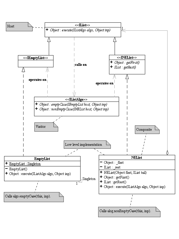
Here is an example of a UML class diagram that holds most of the more common features:
| UML Class Diagram |
|---|
 |
Glossary
- UML:
-
Unified Modeling Language, developed by the Object Management Group ("OMG")
- See Also: Object Management Group ("OMG")