
Working in Rice University's Oshman Engineering Design Kitchen
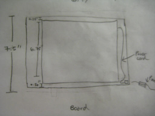
Sketch of the acrylic boards that were used to mount the motherboards to, including dimensions. (These dimensions were later changed to 8" X 8.5")
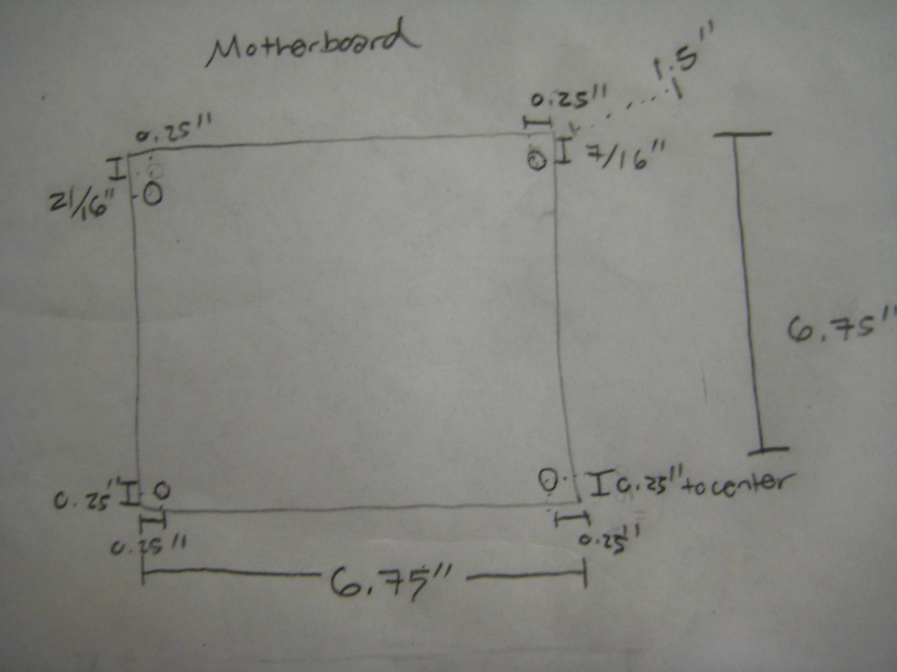
Sketch fo
the
motherboard,
including
dimensions
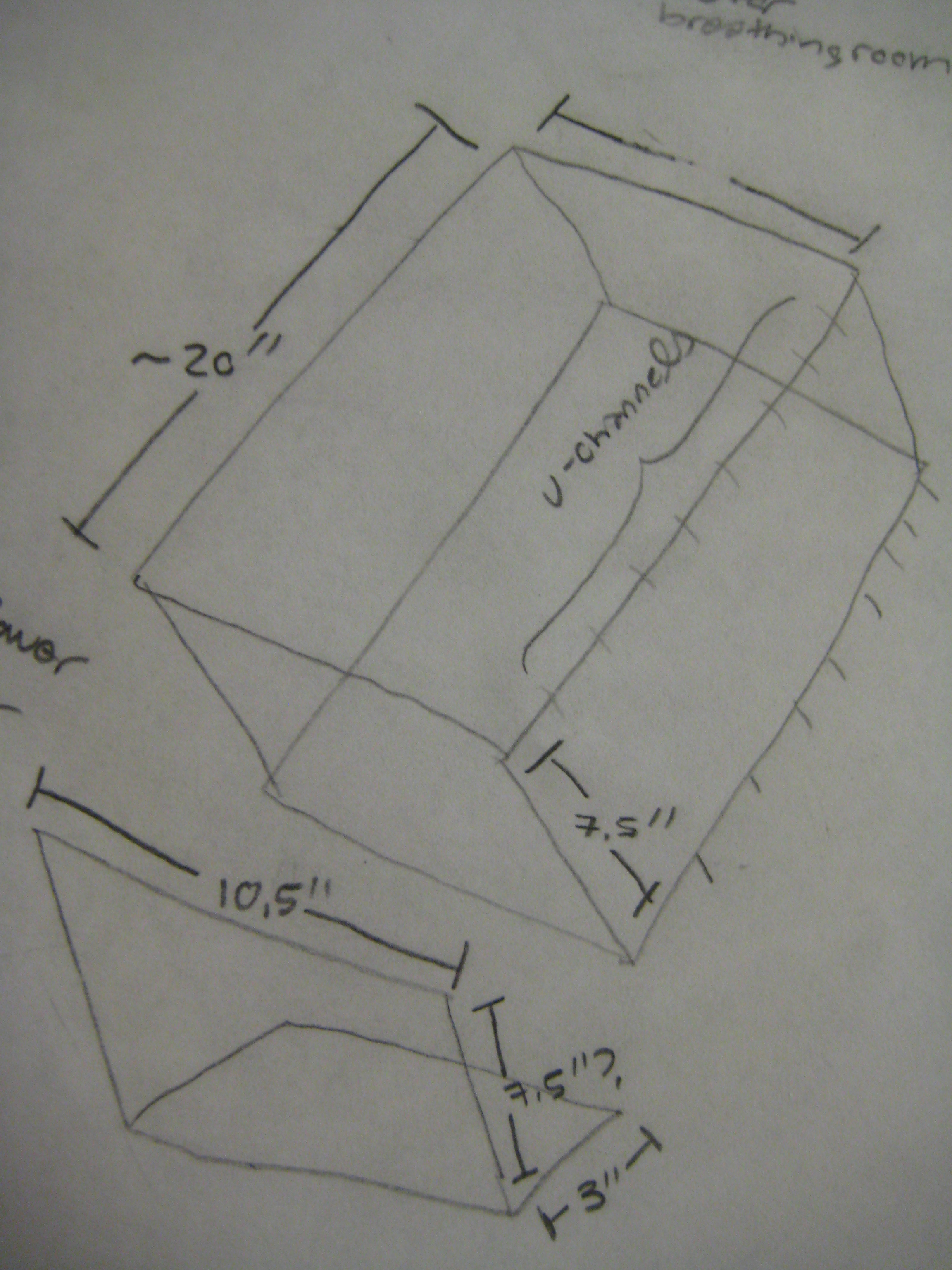
Sketch of the frame, including estimated dimensions
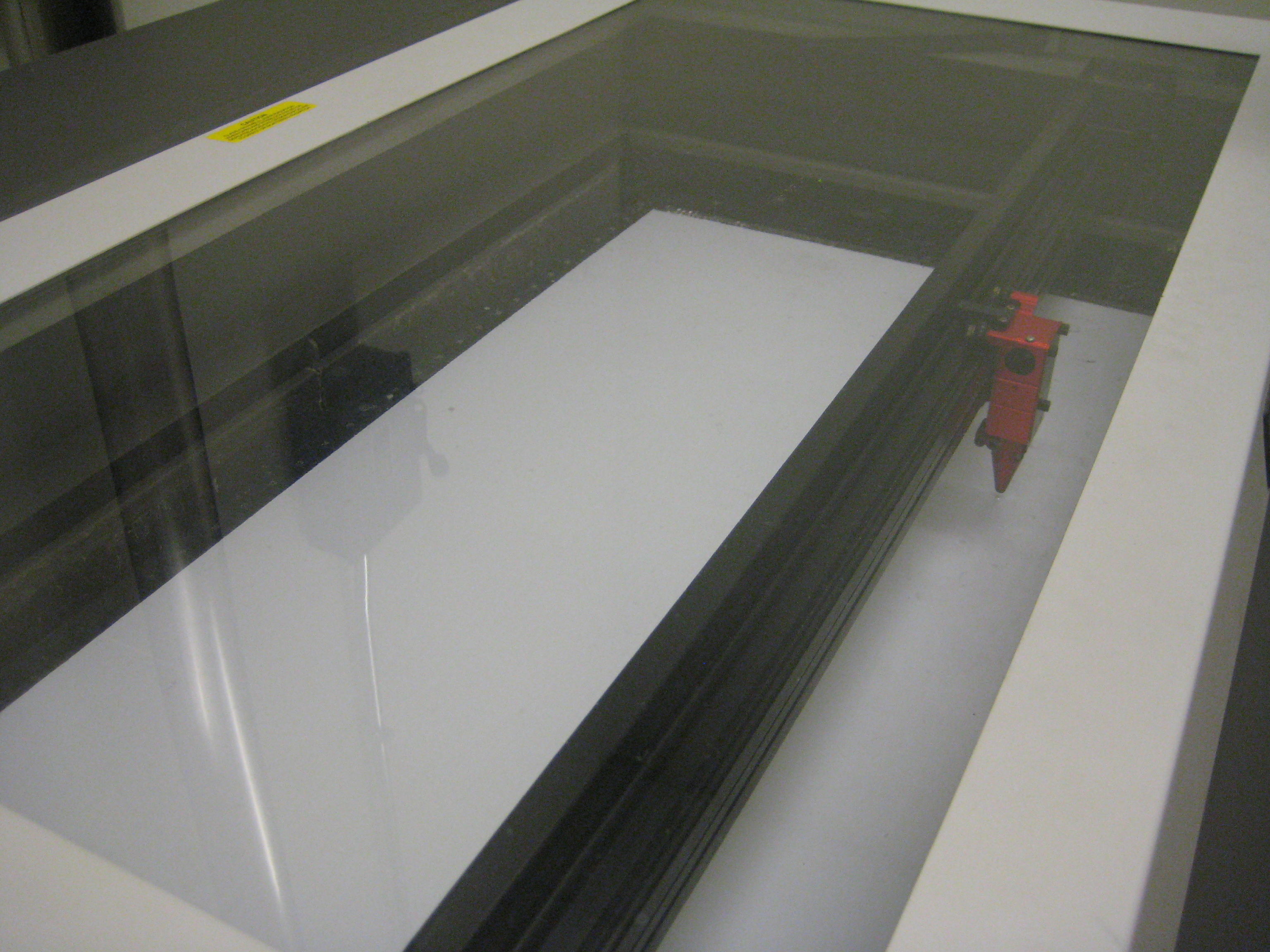
Here, the acrylic board is being cut to predetermined dimensions via Adobe Illustrator.
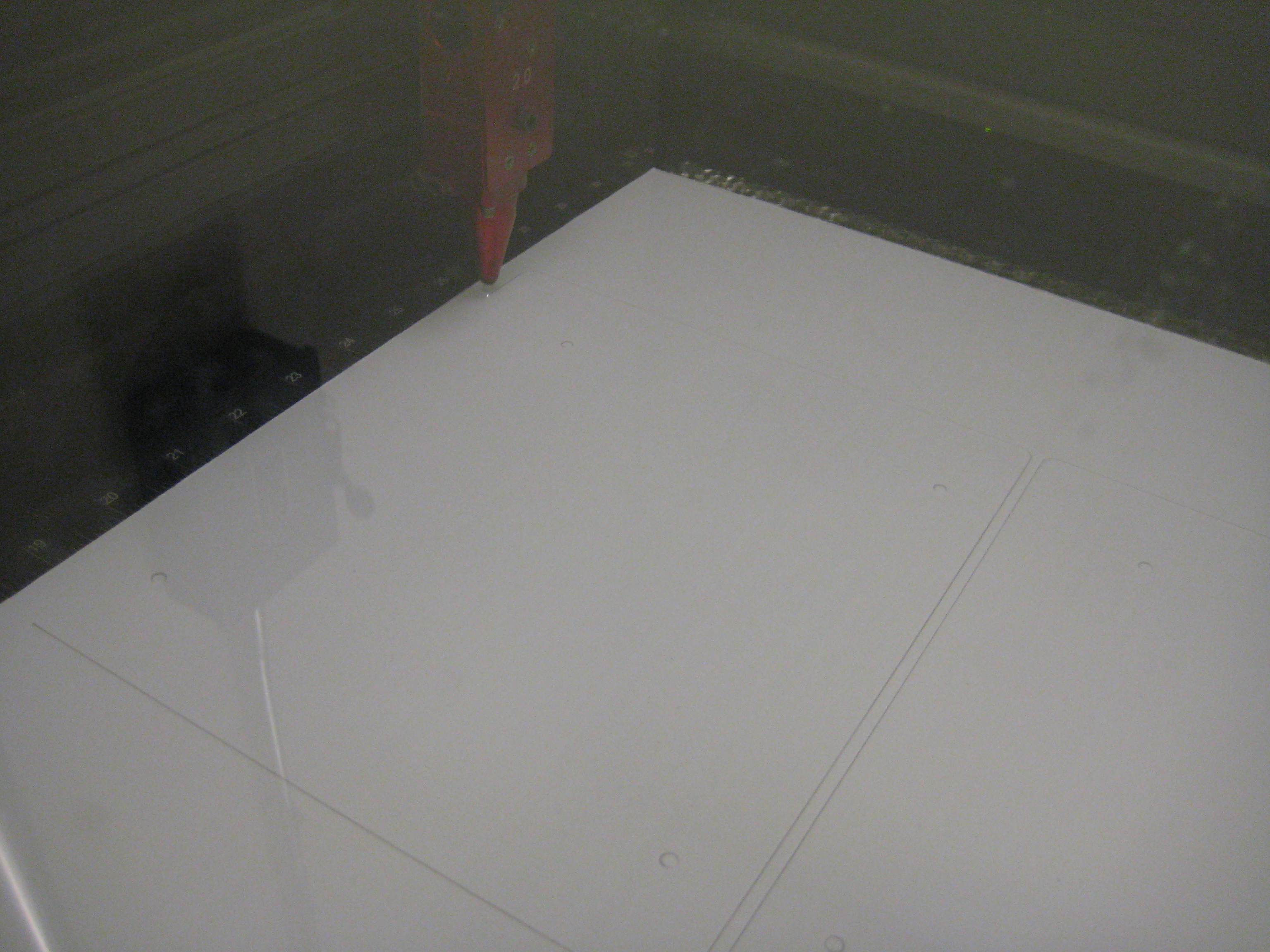
One of our motherboard boards being cut to size.
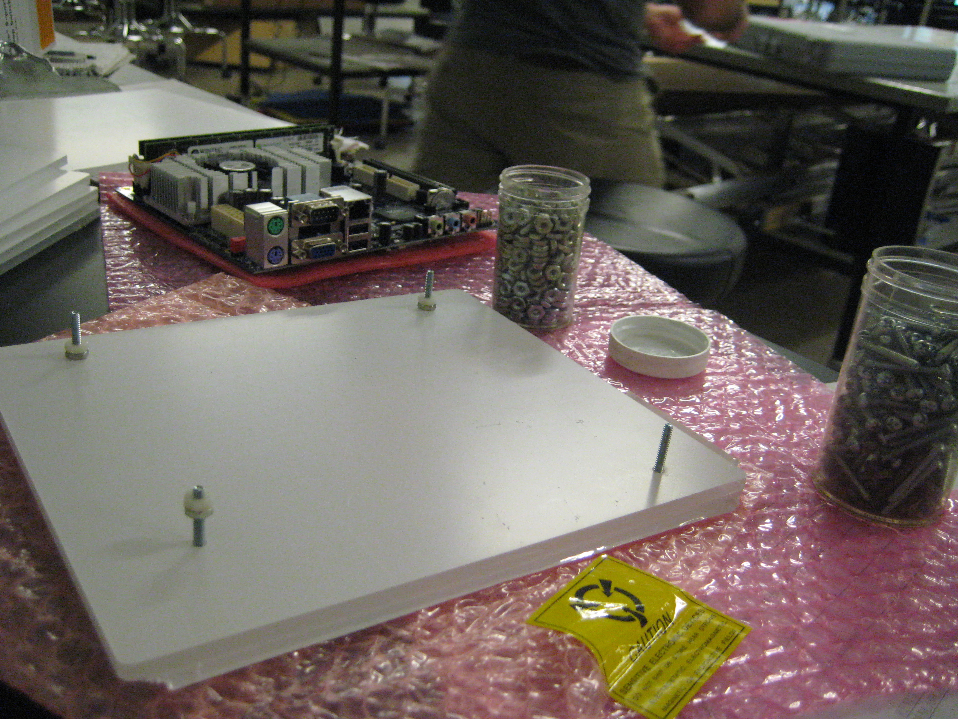
Testing out the size 6 screws, washers, and nuts on the motherboard boards. We landed on using nylon washers and size 6 hardware. We used 3 nuts for each screw: one metal nut against the board below the motherboard, a nylon nut between the metal nut and motherboard, and another metal nut on the top that mounts the motherboard.
After this photo
was taken, the nuts in
between the motherboards
and acrylic boards were
replaced with
custom-made plastic
spacers for a more
professional look.
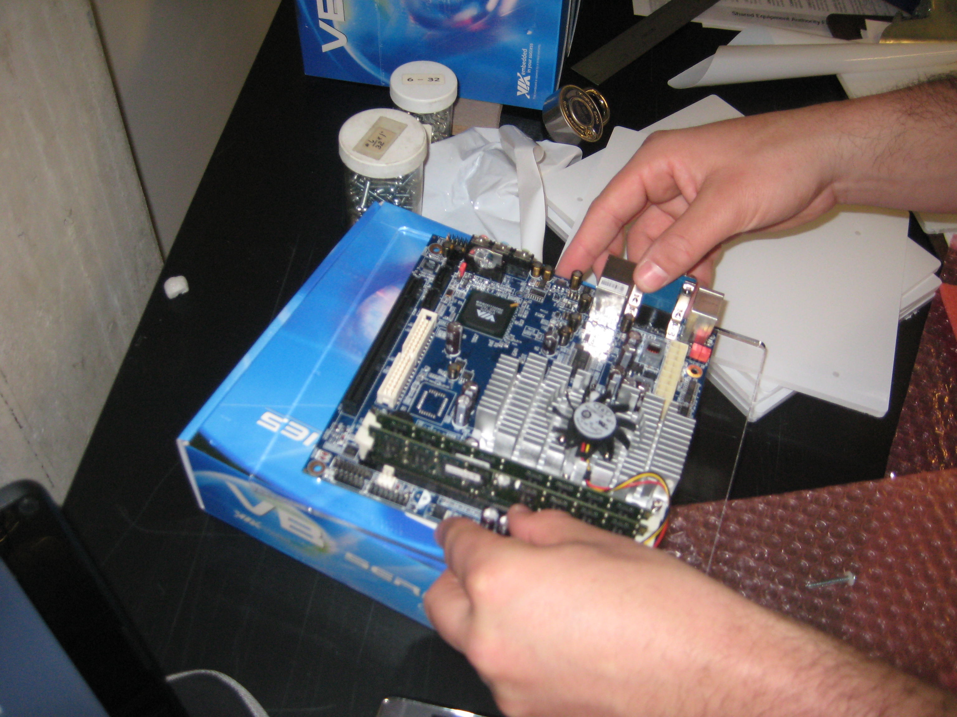
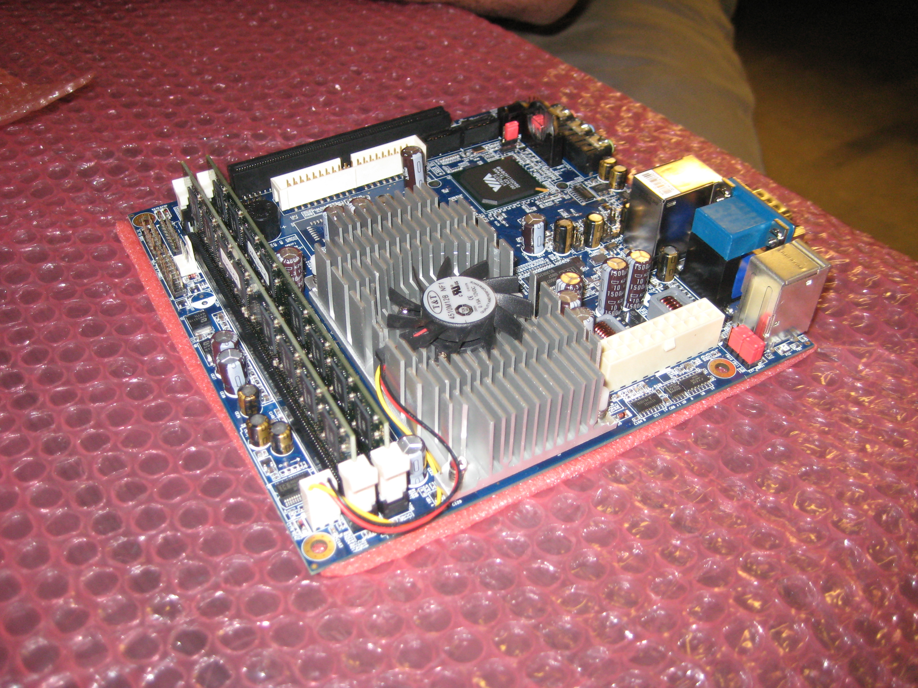
Positioning the motherboard on the acrylic board.
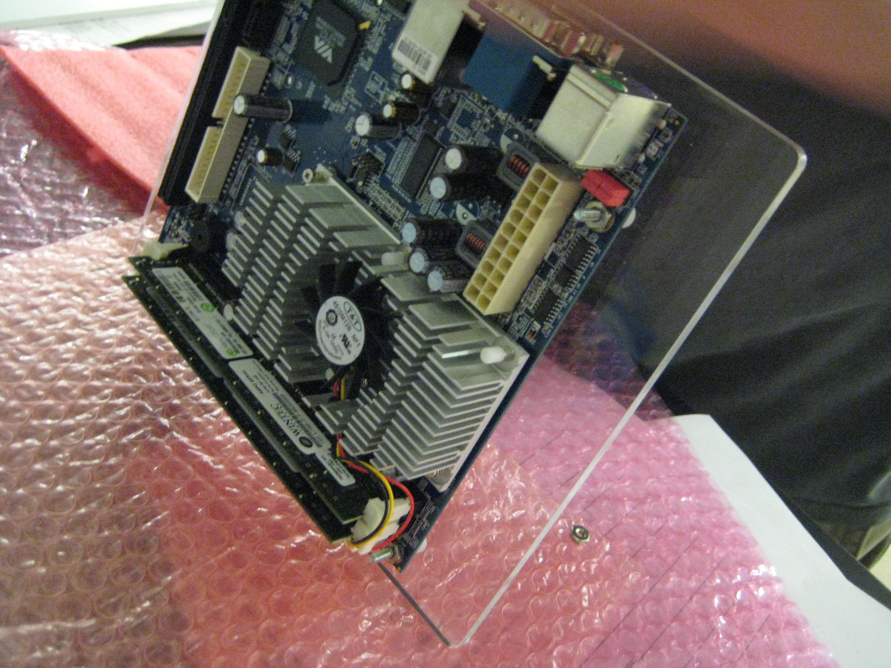
A completed, mounted motherboard.
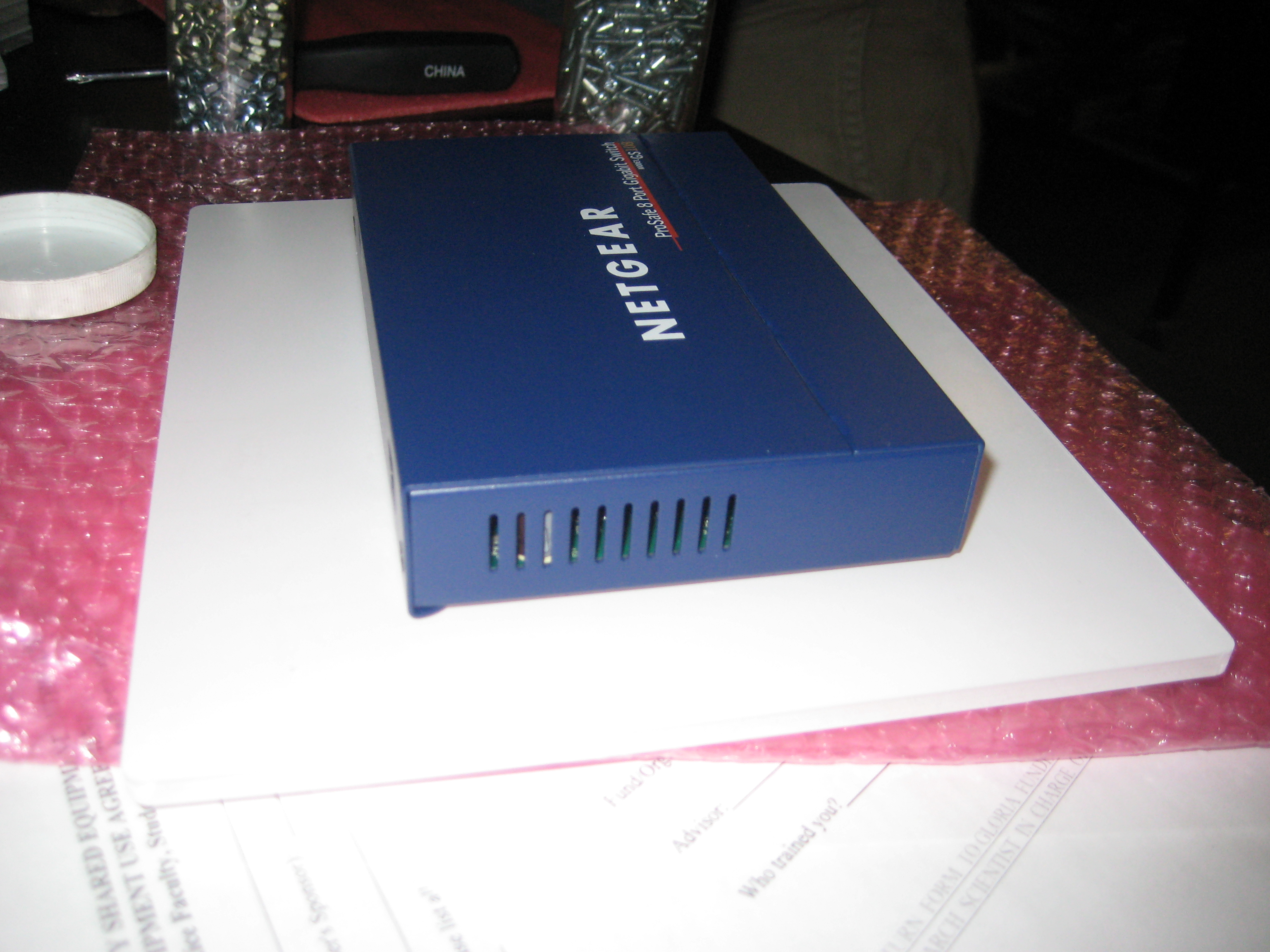
The network box mounted to its acrylic board.
.JPG)
All six mother boards
mounted to the acrylic
boards, which were smoothed
down on the sides.
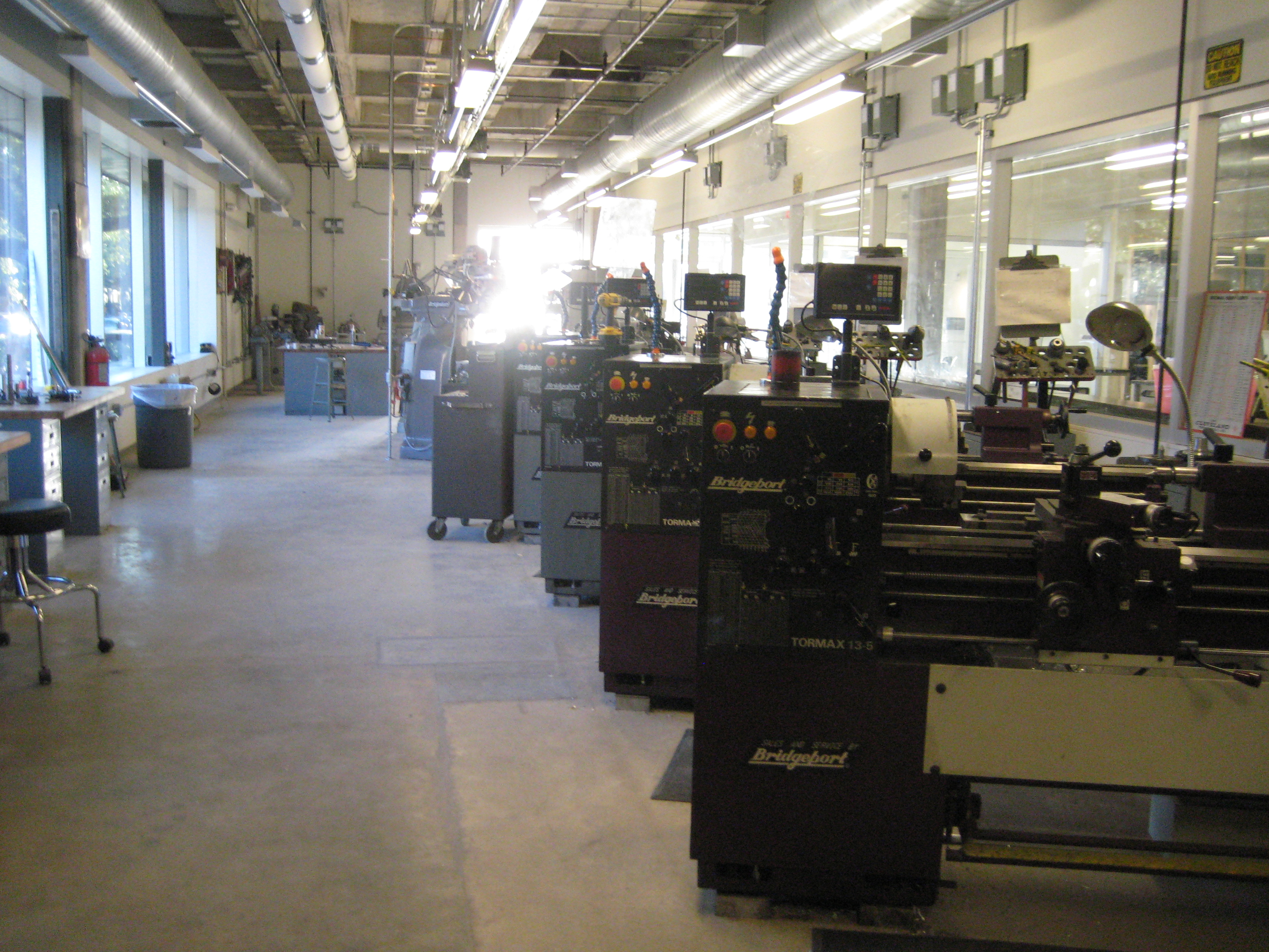
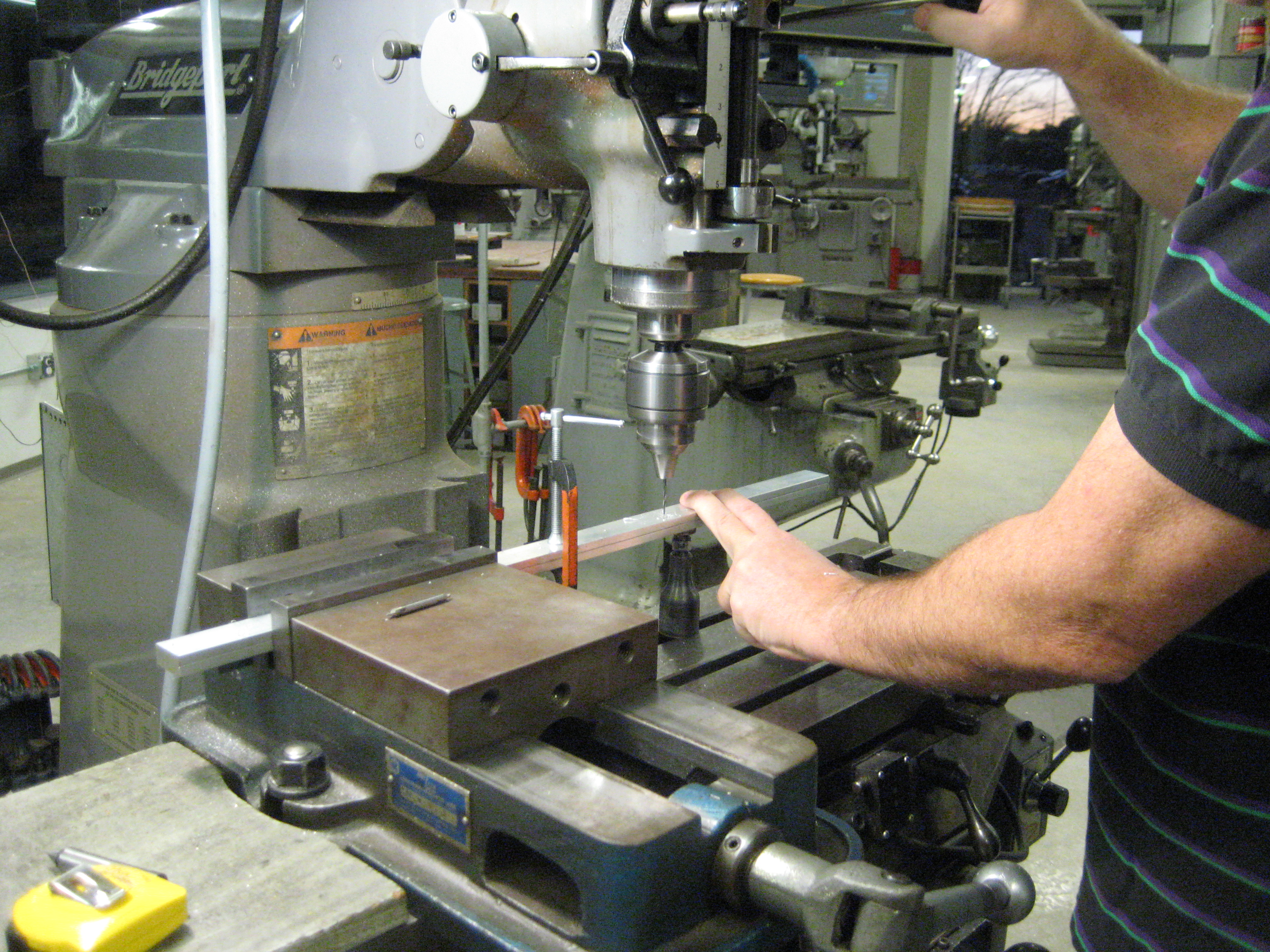
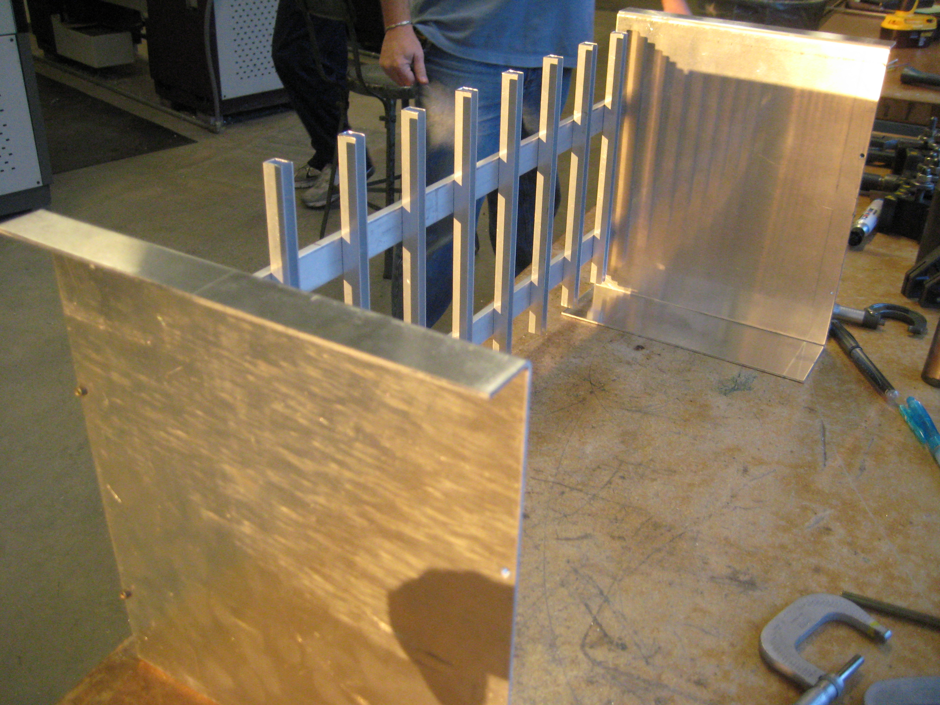
The machine shop
where we will be cutting,
sawing, and milling down
parts for our frame.
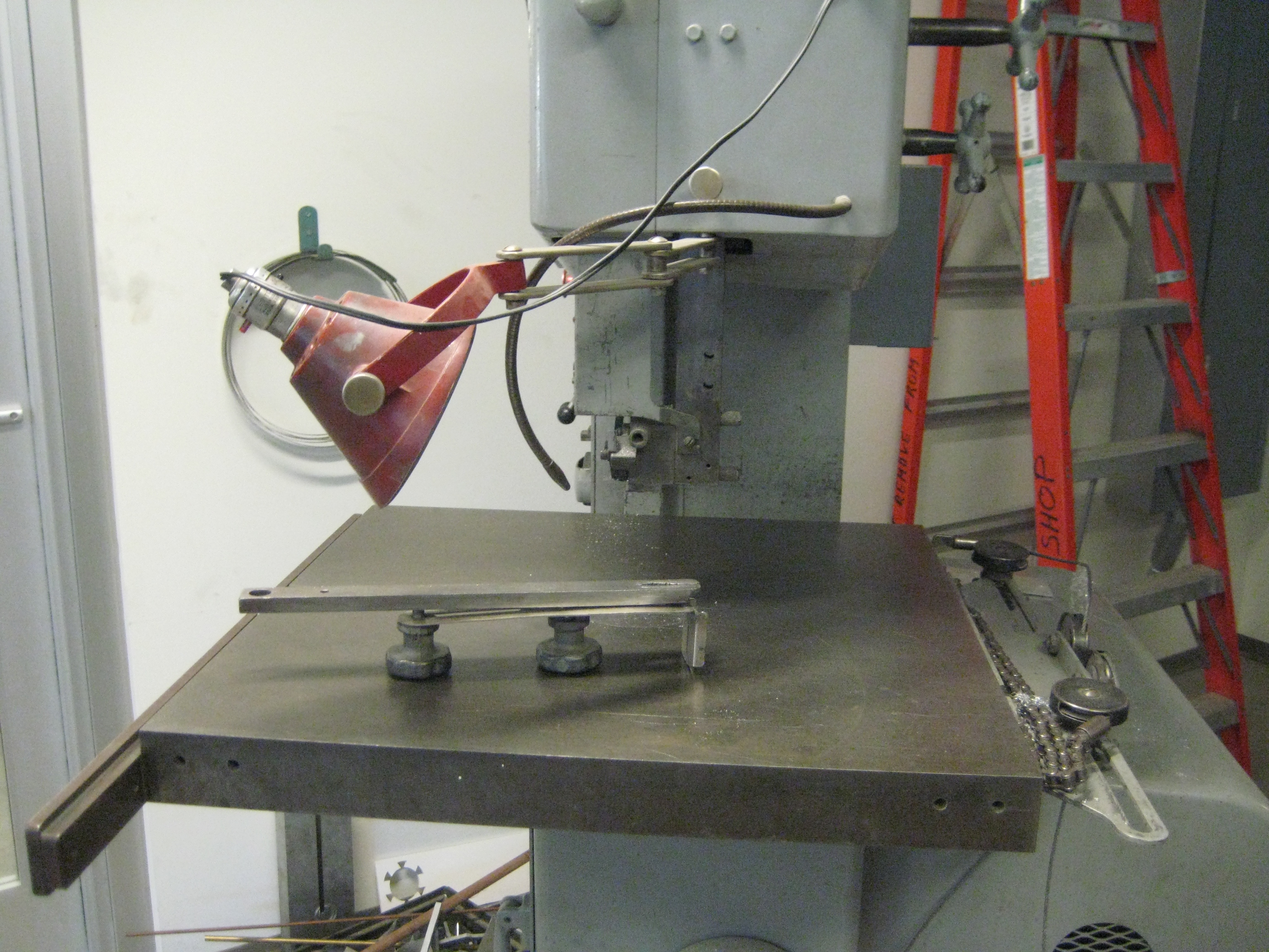
The band saw that was used to cut the U-channels.
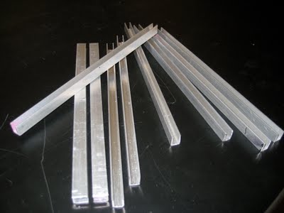
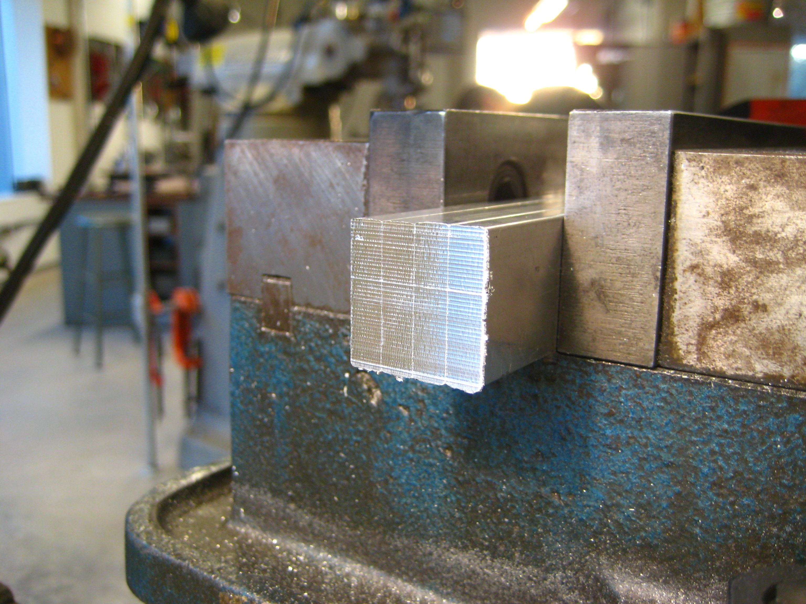
This is a picture of some of the U-channels (16 in total) that were cut by a band saw and then milled and filed down to 9.5" long for a smooth finish.
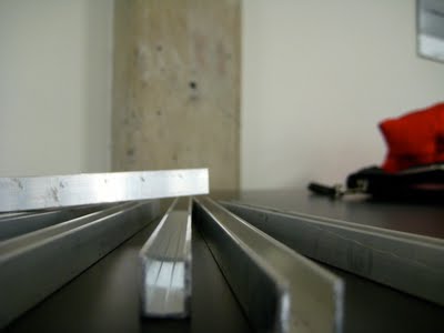
A close-up of the smooth finish on the ends of the U-channels.
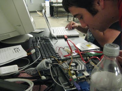
Hooked up the monitor, keyboard, and mouse. Played around with the cables and discussed which operating system to use.
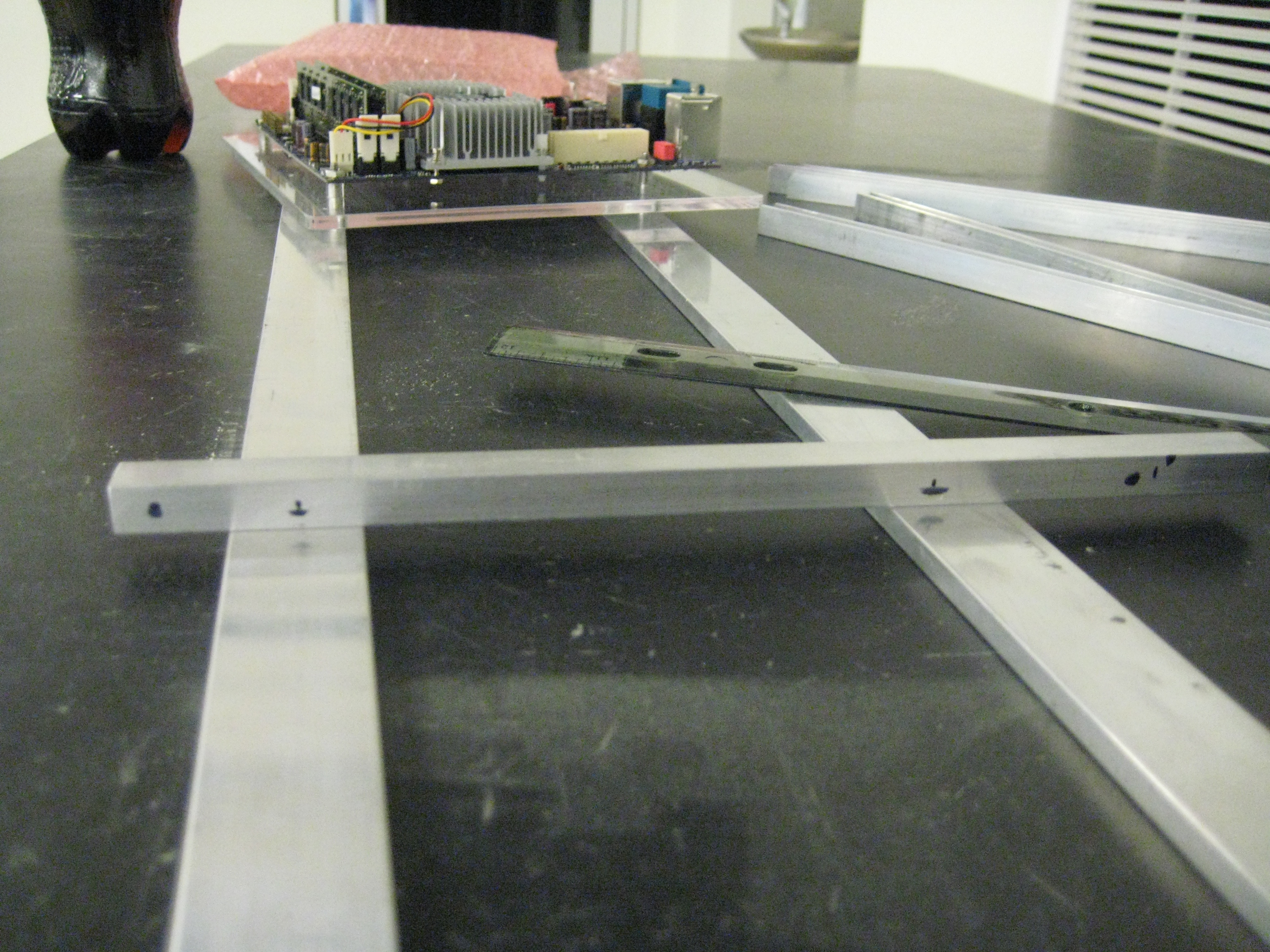
Prepped the U-channels by marking where the holes should go and the spacing of the two side bars.
Decided on 0.25", 1.25", 6.25"and 8.25" from the base and 4" between the two side bars.
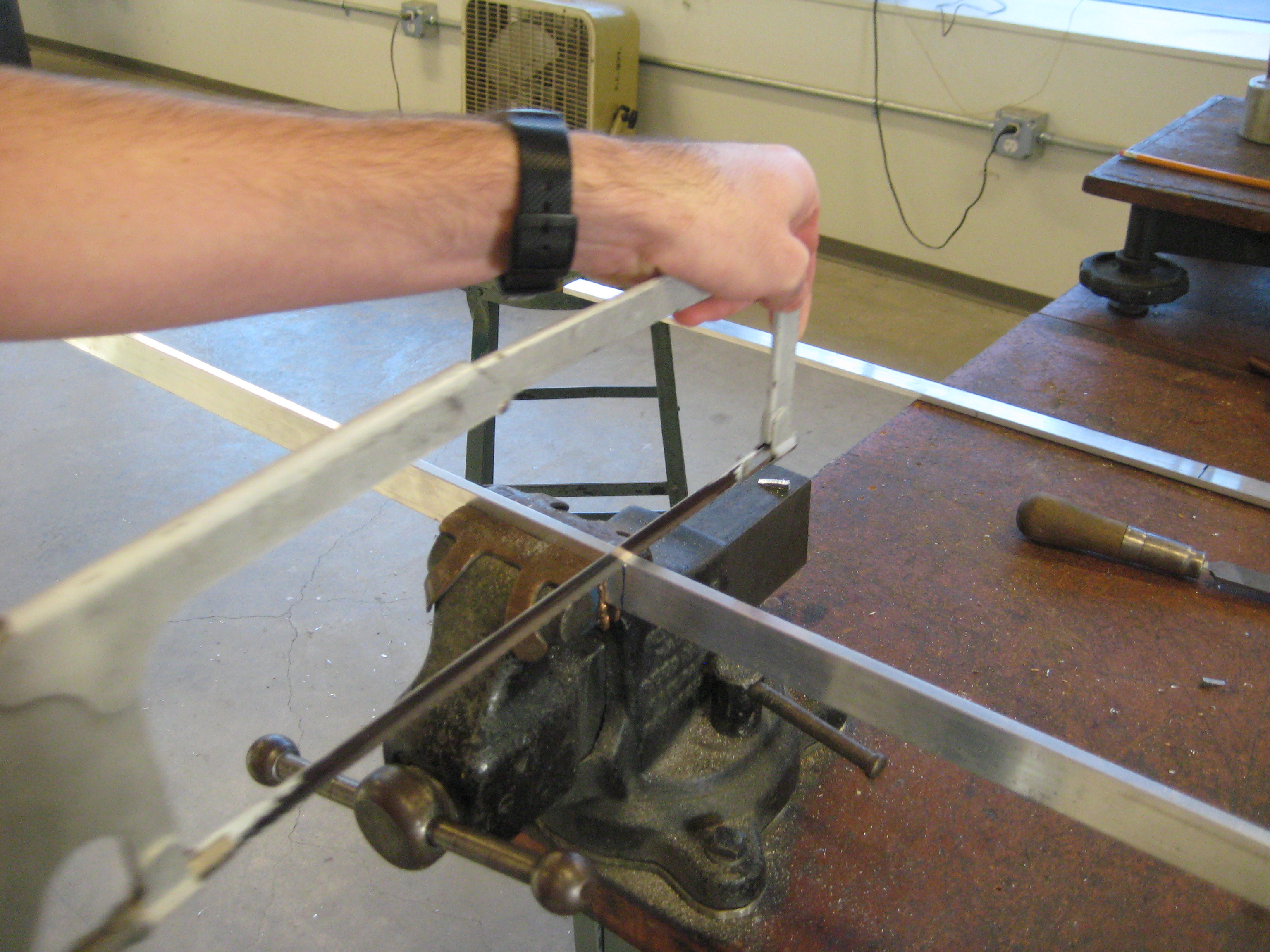
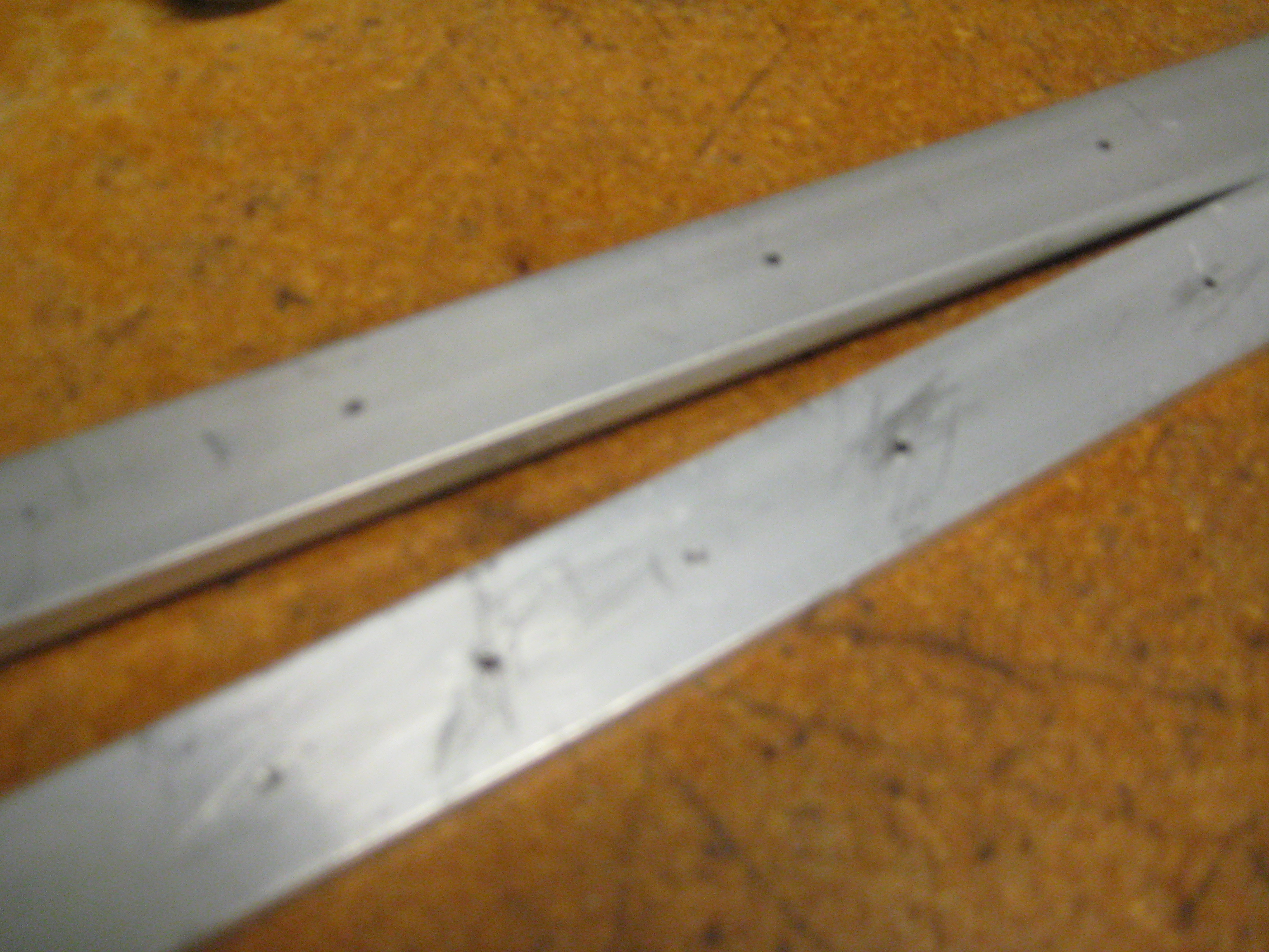
Cut the side rails with a hand saw to
approximately 24" long.
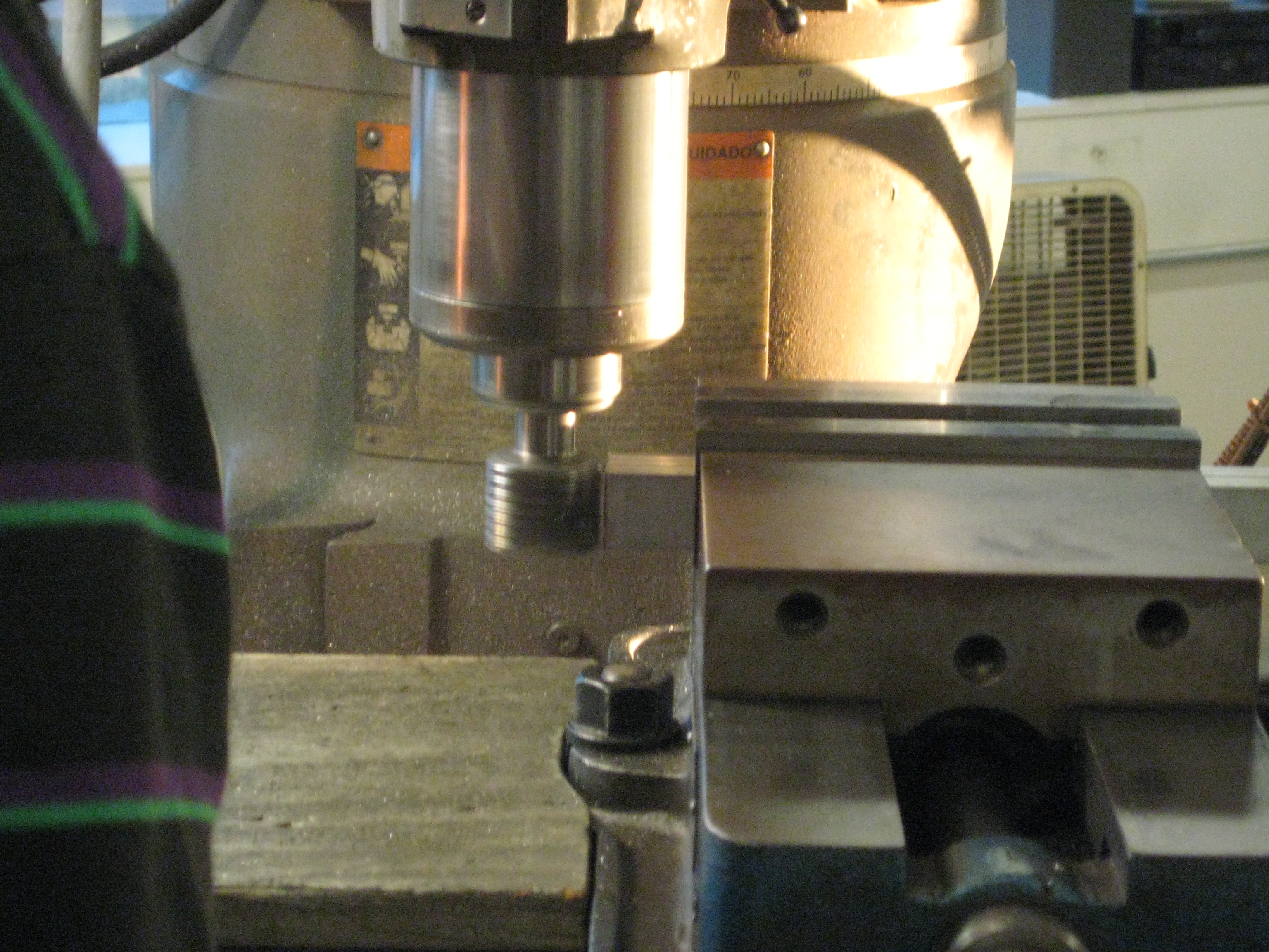
Milled the sides down to get a smooth
finish to 23 3/4" each
After milling, the edges were filed down
by hand.
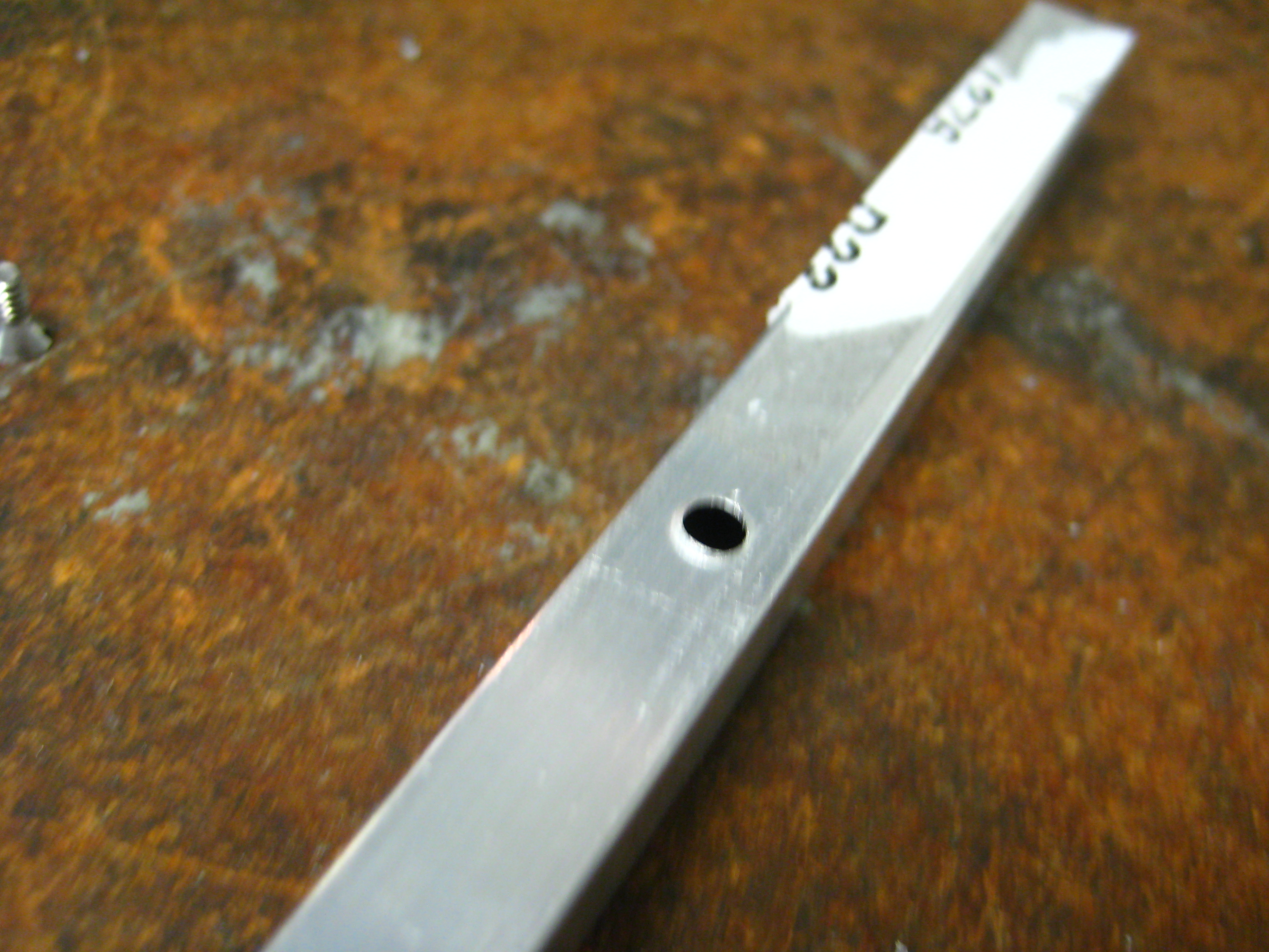
Tested out a small screw size on a spare
U-channel in order to determine what
screw size to be used on the side bars to dill
holes.
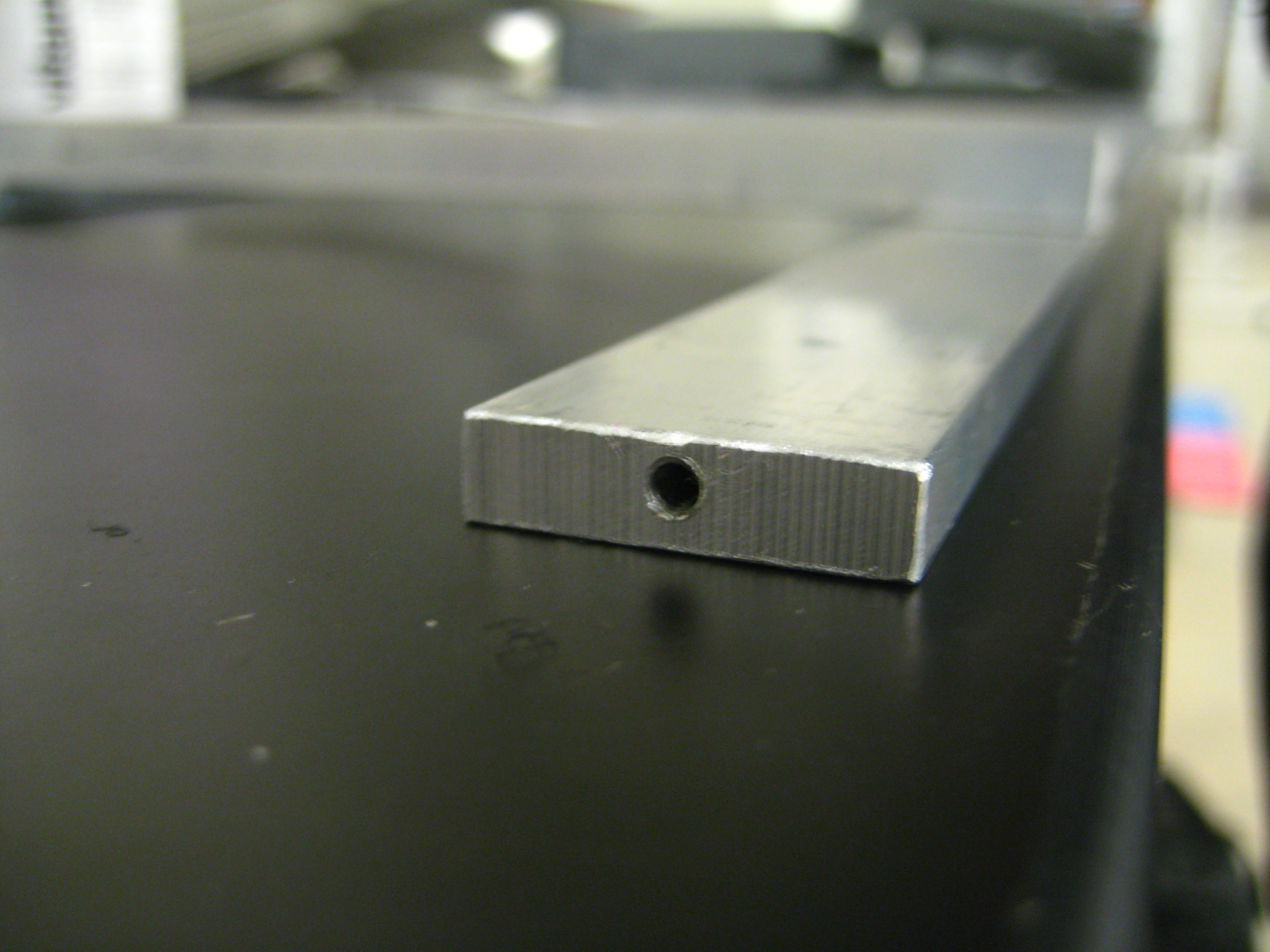
Threaded the sidebars in preparation for screwing them into the base pieces
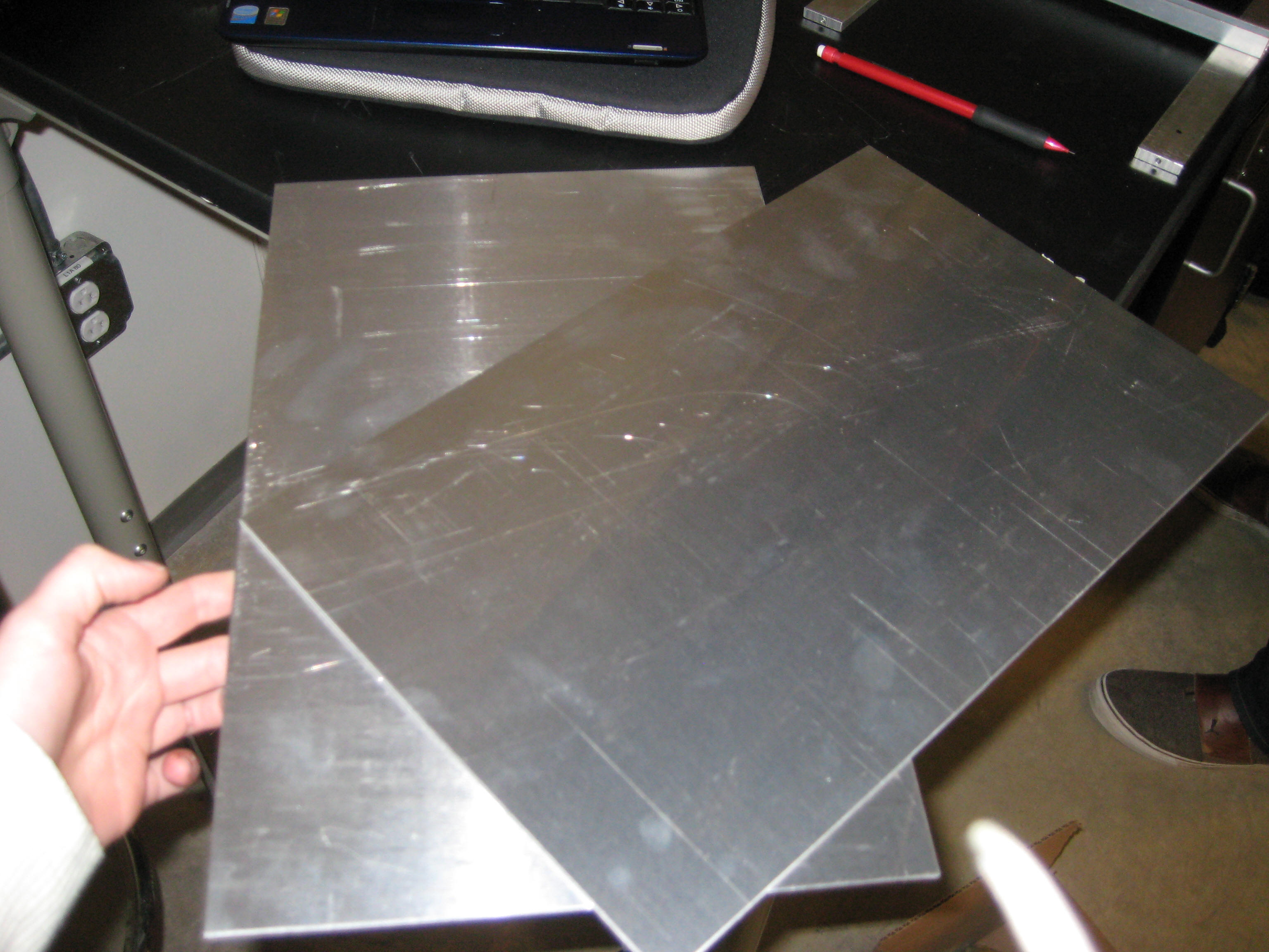
Used a large machine in Ryon Lab to cut 3/32 3003 Aluminum sheets into
2 9.25" X 14.5" pieces for the base pieces, which were then
bent at 3" and at 13.5" (opposite side bent)
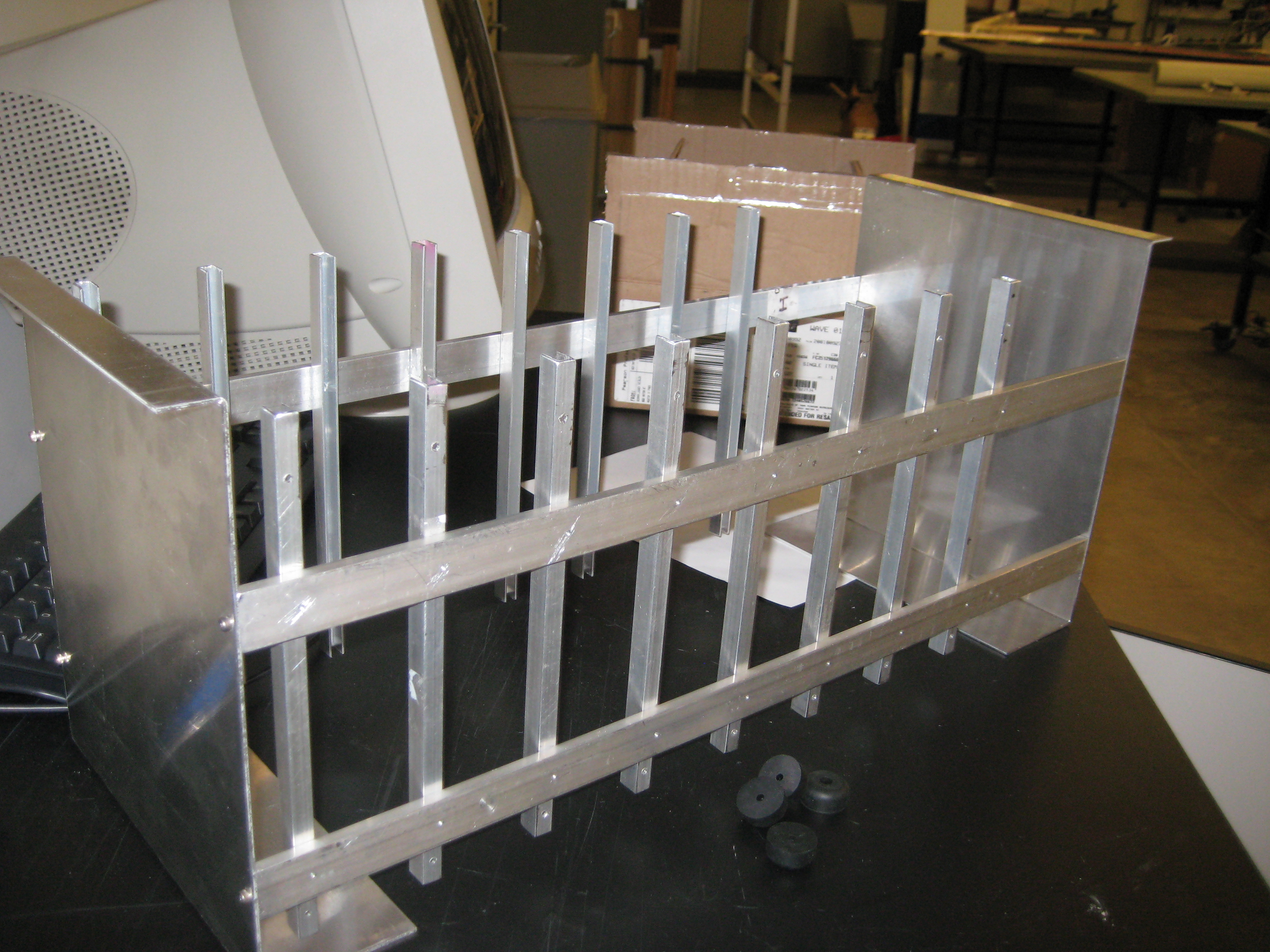
After mounting all the U-channels onto the sidebars, the sidebars were
then connected to the base pieces.
The completed case. :)
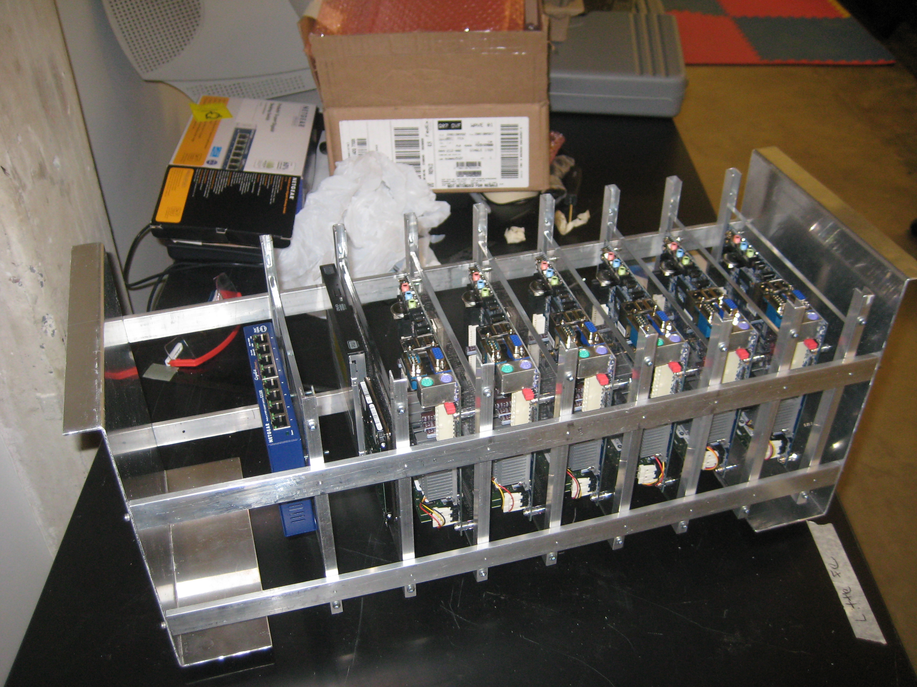
The case was completed. The acrylic boards had to be cut 1/4 of an inch and the
screws for locking the boards into place were threaded into the side
rails (6/32 half inch nails).
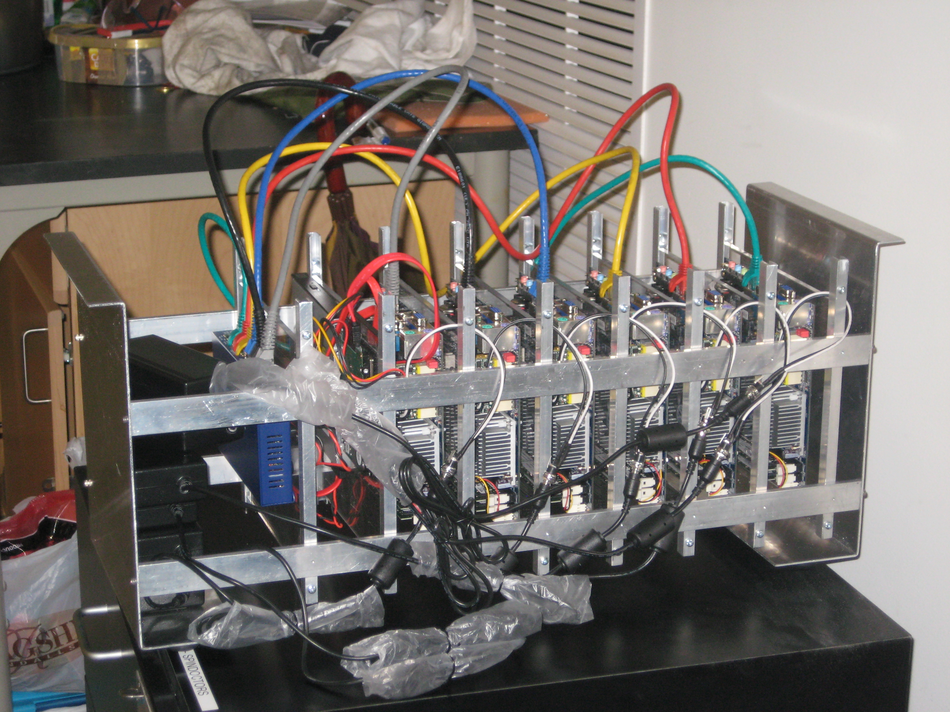
The case with the power supplies, network cables, and power cords connected
to the computers.
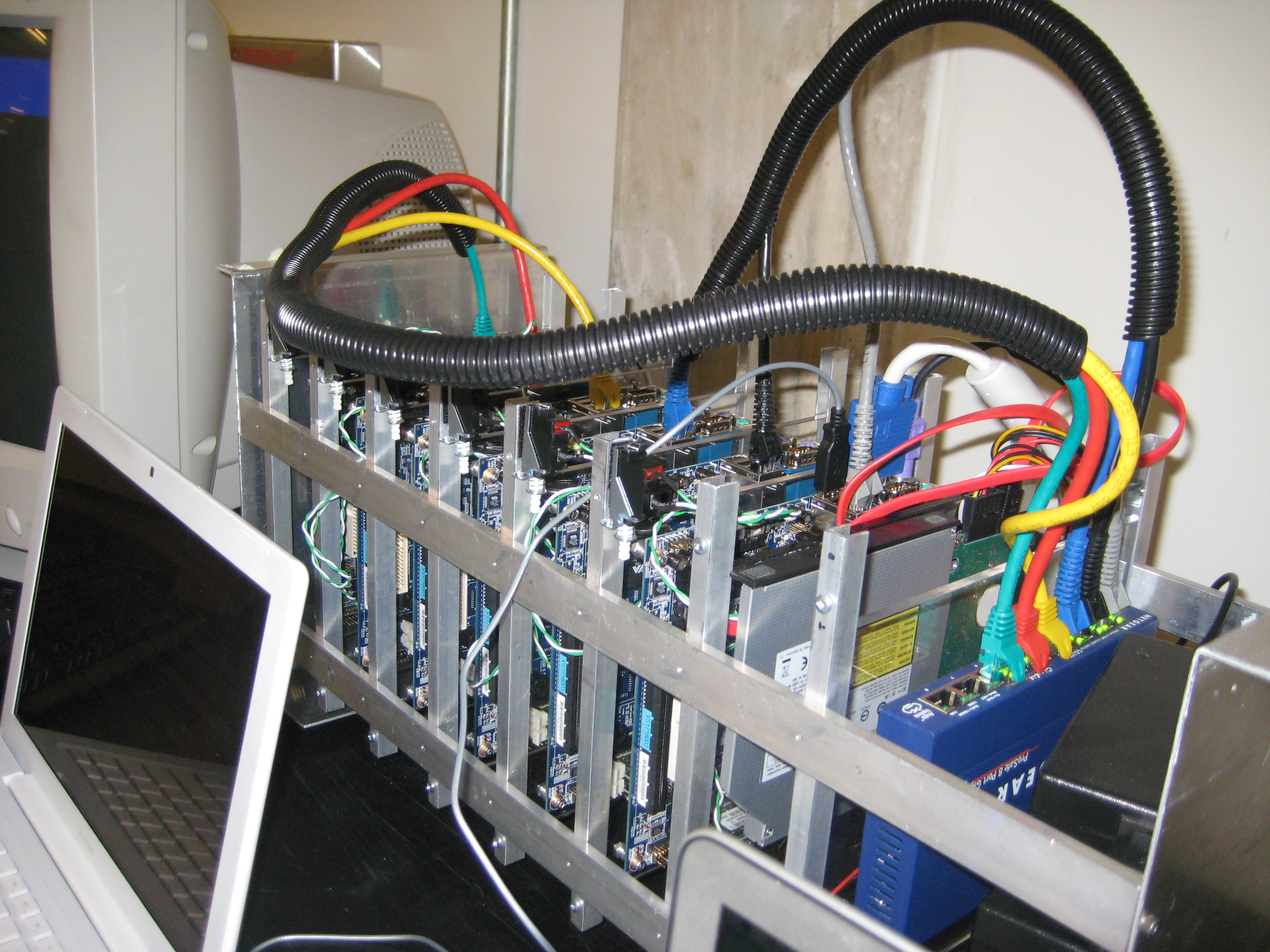
The completed case with cords and power supplies attached.