The problem arises because the signal design becomes a compromise between range and velocity accuracy. A narrow signal provides for better range accuracy, while a wide signal provides for better velocity accuracy.
Another significant problem is background clutter, which appears in a variety of forms. The signal can bounce off of other objects, such as the ground, other buildings, and even clouds, and return a significant amount of noise. The SNR is therefore commonly below 1.
Our goal is to develop a radar system which accurately extracts the range and velocity of several point targets. Each of these targets will return signals with noise. We have chosen the parameters of our simulation and targets to match the parameters likely to be found in an air traffic control (ATC) application.

Our first step in developing our radar system is to determine which signal
we will use for transmitting. As stated earlier, a narrow signal provides for
better range accuracy while a wide signal provides for better velocity accuracy.
An important signal used in radar detection is the linear-FM (LFM) chirp. It
is defined by the formula:
s(t) = e ^(j*pi*W*t^2/T) -1/2T<= t <= 1/2T
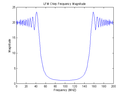
W is the swept bandwidth of the chirp and T is the total signal time duration. The chirp is complex valued because it forms the baseband form of the linear frequency modulation. It is basically a pulse with a time duration equal to T. Over the duration of the pulse, the frequency sweeps from -1/2W to +1/2 W.

Since the duration of the chirp can be long, it can illuminate a target with a substantial amount of energy, increasing range detection. In addition, the matched filter response of the chirp is an extremely sharp, narrow pulse which is perfect for distinguishing closely spaced targets. While the chirp is very useful in range detection, it is not a good choice for velocity measurements.
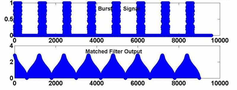
For precise velocity measurements, we need a signal with a high pulse repetition rate. This signal is called a burst, a waveform made up of repeating short pulses. For our radar system, we have chosen a burst of chirps (pulses) as our transmitting signal. This should provide accurate velocity detection and since the maximum range of our targets is not large, we should also obtain accurate range measurements.
To create the burst wave in Matlab, we start with a single chirp signal. In the function dchirp, we make a chirp function with the parameters T, W, and p (where the sampling frequency = p*W). In the function burst, we call the dchirp function to create a burst or sequence of chirp functions. The parameter M is the interpulse period, N is the pulse length (N = pTW), and L is the number of pulses. We add noise to the burst signal using the randn command. The noise level can be set using the n parameter.
For our project, we will use a burst with 8 pulses (L=8). The time duration (T) of each pulse will be 128 microseconds and the sweeping bandwidth (W) will be .5 MHZ.
In order to process range information, we must use a matched filter. Our match function in Matlab utilizes the Fast Fourier Transform Algorithm for convolution. The matched filter output allows us to detect the returned burst. We can then us the time delay in the returned signal to calculate range.
Range= 1/2c * time-delay
We can extract range information from our matched filter by looking at the peak output values. Our function findme takes the output of the matched filter and determines where these peaks occur. Peaks should occur in sequences of eight since our transmitted signal is a burst consisting of 8 pulses. However, we are only interested in where the first of these eight peaks occurs. The function pickme selects the first peak giving us the range indices. Our function range finally takes these indices and calculates the range according to the above equation.

In order to process velocity information, we must take into consideration the
Doppler frequency shift caused by a moving target. We must therefore perform
a spectral analysis of our burst signal. The Doppler frequency shift caused
by a moving target with velocity v is defined as:
In order to determine the phase shift of the returning signal, we look at the signal where it is changing the most. We want to use the same point on the original and the returned signal to calculate the change in shift. We choose two threshold to compare. These points are the midpoint indices between the maximum and the minimum points of the signals. The function velcalc finds these indices and calculates the difference in phase between the received and returned signal. Using this information and the range index, we can then calculate the velocity using the Doppler equation.
In order to test our system, we simulate test return signals using our doppler function. The function CTV.m calls doppler.m and creates a a vector containing the ranges and velocities of up to three targets. In test.m we create an array of ten targets using CTV.m. We place some of these targets in the same 3 degree block to show that our radar can still find multiple targets in its scanning angle. We add noise to each of the return signals so that the SNR equals 1.25. We are finally ready to test our radar system. The function simradar puts together our velocity and range processing algorithms and gives us our final result.