Issue 3
The Encoding Algorithm
Issues 1 & 2 taught us very clearly that we ought to use the DCT domain and hide our data in the low to mid frequencies. Our next question is simple: how are we going to encode data into the DCT domain? Somehow, we have to encode a simple text message into the picture and ensure that it will withstand the printing process.
Convert String to Binary
Our first task was to convceive a method to convert our message to binary. We rationalized that with 5 bits per letter, we could encode 32 different characters. This would give us the whole alphabet as well as 6 other characters. Instead of limiting ourselves to only 32 characters, we chose to encode 6 bits per character. This way, 64 different characters can be encoded into the image. This algorithm includes every letter, every number, and almost every symbol on the keyboard. The conversion from text to binary is done in binaryencode.m .
Break Up the Image
When an image is converted to JPEG, the first step is to split up the image (in the spatial domain) into 8x8 blocks. These blocks are then processed individually and put back together in the end. We decided to apply a similar process to our encoding algorithm. Similarly, we split up our image into 4 equal quadrants. In this way, we can process each of these quadrants independently and virtually increase our bandwidth.
Discrete Cosine Transform
The next step is to convert the image into the frequency domain. This process is done using a two-dimensional discrete cosine transform. Our picture is basically a matrix of data, so MATLAB makes this process rather easy. Keep in mind that each of the four quadrants are processed seperately, and the DCT is taken on each quadrant.
The ONEs and ZEROs
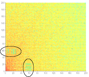
We now have to put the ones and zeros into the image. Our picture holds a total of 96 bits. Moreover, that means each quadrant must have 24 bits encoded within it. Out of these 24 bits, 12 bits are encoded near the horizontal axis of the DCT, and 12 bits are hid hear the vertical access of the DCT. Data is hidden in 16 bit long blocks of coefficients. On the horizontal axis, these blocks are encoded on every even row from 2 through 24. On the vertical axis, these blocks are encoded on every odd row from 3 through 25. To encode a "1" all the coefficients in a block are divided by the absolute value of their magnitude. Basically, if the coefficient is positive it becomes a 1, and if it is negative it becomes a -1. To encode a zero, no change is made to the block. These blocks are seen clearly in the picture above!
Inverse Discrete Cosine Transform
We are now finished with the frequency domain! To get back to the spatial domain, it is necessary to take the Inverse Discrete Cosine Transform on each of the 4 quadrants. Again, MATLAB makes this takse easy.
Put the Pieces Back Together
Each of the four quadrants now have 24 bits encoded within them. To get back the semblance of our original image, all we have to do is put back together these four pieces in the same way we took them apart.
Print!
YAY! We are done with the encoding process. A 96 bit message is now encoded into a picture. Print it out, and let a friend decode it!
The Decoding Algorithm
So now we have an encoded image. It's been printed. It's been scanned. Somehow, we have to extract a text message from this image. The decoding process undoubtedly is the most difficult part of the project. In principal, the decoding process is intended to be the inverse of the encoding process, and it truth that is all it really is. However, the printing and scanning cycle adds quite a bit of noise to the image, and a significant amount of processing needs to done to retreive our bits.
Break Up the Image
Break up the image into 4 equal quadrants. This step is done in exactly the same manner as in the encoding process.
Discrete Cosine Transform
Take a two dimensional discrete cosine transform of each of the 4 quadrants. Again, this is done in exactly the same way as in the encoding process.
The ONEs and ZEROs
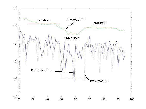
In the encoding process, whole blocks of coefficients were changed to 1 if a 1 bit was encoded. No change was made to coefficients if a 0 bit was encoded. The goal in the decoding process is to find these bits! The above graph shows the value of DCT coefficients along one row. A 1 is encoded in this row. Moreover, it can be seen by looking at the original encoding in the "Pre-printed DCT" that the coefficients values from 50-65 were all changed to 1. When looking at the "Post-printed DCT" values, it is readily seen that the printing and scanning process adds quite a bit of noise to the original encoding. The goal here is to find dip in the values of the coefficients from 50-65. A smoothing filter is applied to the "Post-printed DCT" values, and this "dip" is made readily visible in the "Smoothed DCT" values. The trick now is teaching a computer to decipher a dip that our eyes can see so clearly. To do this, we find three means. The "Middle Mean" is the mean of the middle 8 values of the 16 DCT coefficients in the orignal block. The "Left Mean" and the "Right Mean" are the means of the 24 DCT values preceding and following the 16 coefficient block. The ratio of the Middle Mean and the average of Left and Right Means tells us the value of our bit. If the ratio is small enough, we have 1, otherwise, we have a zero. This process is repeated for all the rows and columns in all the quadrants where data was originall encoded.
Convert Binary to String
So now we have a long vector of ONEs and ZEROs. All we have to do is convert them to characters to get our original message back. Remember that every 6 binary bits decodes 1 character.
Rejoice
Hopefully, if the process was done right, you should have get back the original message that was encoded in the picture. Unfortunately, if only for every bit error, you are likely to get a whole character wrong. Just cross your fingers and hope for the best!