Testing Summary
Omnilab Setup
The equipment used for testing includes the stimulus generator,
logic analyzer, and breadboard. The stimulus pins are connected to
the chip inputs and to the logic analyzer pins. The chip outputs
are monitored using the logic analyzer.
Test Vectors
The test vector is a concatenation of three games, allowing the
low-score feature to be tested. The first game is won in two
guesses. The second game is lost when the guesser exhausts the
number of guesses allowed (seven). This game is designed to test
the scoring capabilities of the chip by inducing a variety in the
number of black and white scores. The third game is won in one
guess, lowering the low-score component to one.
Functional Testing
All five chips are fully functional. The Omnilab
results match the
IRSIM results obtained last semester, indicating the unexpected
adequacy of the simulation capabilities of IRSIM. In testing the
entire chip, IRSIM indicated a few current leakage errors that were
corrected before fabrication.
Omnilab Results
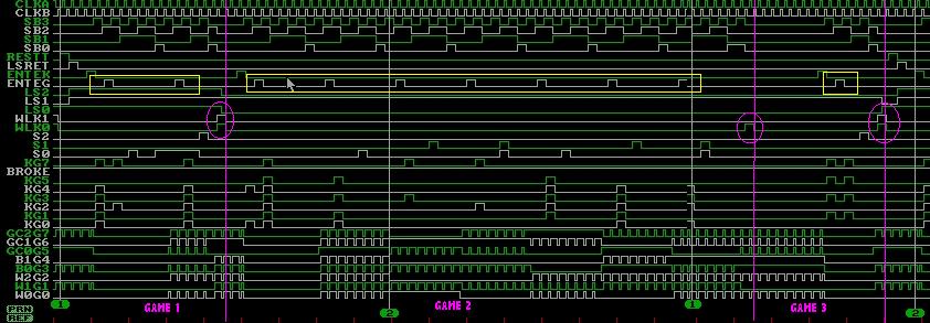
PINK: win-lose-keep gussing output. YELLOW: enter guess signal.
Speed Testing
Using the non-overlapping clocking scheme, the chip fails at
approximately 8.5 MHz (34 MHz sampling rate). The failure location
is in the output multiplexer, which displays the current guess and
score. This failure does not impact the performance of other parts
of the chip; the Omnilab analyzer output shows that the chip
continues to go through the proper states at this frequency.
Non-Overlapping Clock
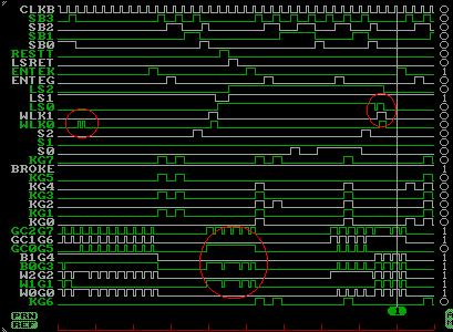
RED: errors
A possible reason for the output multiplexers failure is charge
sharing. The transmission gates of the multiplexers are
controlled by clka and clkabar, so the values at each of the
outputs are only transmitted at selected times. Since clkabar is
generated from clka through an inverter, the delay could be causing
charge sharing at the connected output of the transmission gates.
Using an aggressive clocking scheme (one clock rises as the other
falls), the chip similarily fails at 8.5 MHz (17 MHz sampling
rate).
Aggressive Clocking
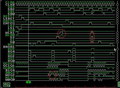
RED: errors
Possible Improvements
One improvement would be to redesign the multiplexers so that they
are capable of switching at higher frequencies.
To make playing the Mastermind game more interactive, a graphical
user interface could be designed for real-time play.