Algorithm |
Addition &
Subtraction |
Algorithm |
Addition &
Subtraction |
Booth Recoding & Radix-4 Overview
Booth recoding is a method used to allow signed binary numbers to be multiplied as if they were unsigned numbers using addition, subtraction, and shifting. It works for a multiplications of A x B by examining the least significant bits of A to determine whether or not to add or subtract multiples of the multiplicand. A more detailed discussion of Booth Recoding can be seen in [x] by Hennessy and Patterson.
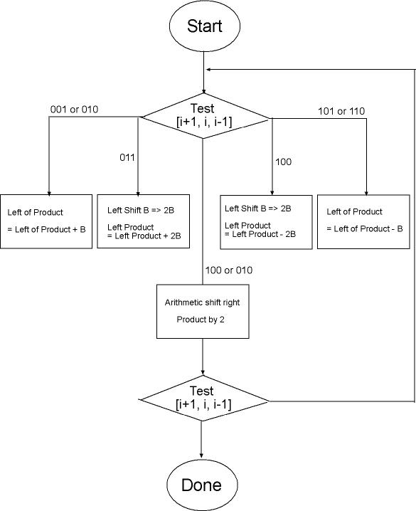
We are using Radix 4 Booth Recoding, which has an improvement over standard recoding in that instead of examining just the LSB and the last bit shifted out of A, it examines 2 LSBs as well as the last bit shifted out. This allows for the possibility of 2B or -2B as the summand in performing the multiplication and cuts down the number of add and shift operations that have to be performed. The table detailing the multiples of B to use for Radix-4 Booth Recoding is shown below.
Multiples of B used in Radix-4 Multiplication
| Low Order bit of A | Last bit Shifted out |
Multiple |
|
| i + 1 | i | i - 1 | |
| 0 | 0 | 0 | 0 |
| 0 | 0 | 1 | +b |
| 0 | 1 | 0 | +b |
| 0 | 1 | 1 | +2b |
| 1 | 0 | 0 | -2b |
| 1 | 0 | 1 | -b |
| 1 | 1 | 0 | -b |
| 1 | 1 | 1 | 0 |
The flowchart below illustrates the steps required to perform Radix 4 recoding. A multiplication will always require four iterations through the loop in this flowchart, but the number of cycles required for each iteration, however, depends upon the operands. As can be seen, if the low order bits of A and last bit shifted out are 000 or 111 the multiple to be added to the product is 0, skipping the addition/subtraction stage and reducing the total cycles.
Multiplication Algorithm Flowchart
We designed our multiplier such that it would take a fixed number of cycles to complete a multiply operation. This was to simplify the timing of our system because we do not have to allow for varying lengths of time for multiply operations to complete. We also designed our multiplier such that it is constantly running and only latches the inputs to the multiplier when we send it a control signal. We divide CLKB by 2 in order to generate a control signal for a second pair of latches in the multiplier that is used to complete the adding and shifting during multiplication. A detailed logic diagram of this system can be seen here.