Given a sampling period Ts, one can cause a note of frequency f to be played by choosing the total number of delay line blocks to be N = 1/(f*Ts). Choosing the value N determines the time it takes for a wave to travel back and forth along the delay line; this determines the fundamental frequency that the delay line supports. Like an instrument with its string or bore set to a particular length, the delay line will also support multiples of this fundamental frequency. A multiple of the fundamental will also repeat after a round-trip through the delay line.
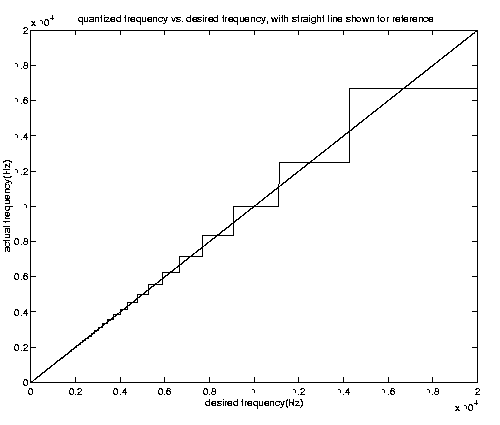
There's a problem with tuning a delay line: you only have an integer number of delay boxes in the delay line. (In fact, if you use a delay line with two 'rails'--one for each the left- and right-going component of the wave--then you can only have an even integer number of delays.) Thus the total round-trip period can only be made to be an integer multiple of the sampling period. Thus, one calculates the delay line length by rounding the number Ts/f to the nearest integer. This leads to the problem of quantized frequency. This is seen in the figure below

It is seen that the deviation from the desired frequency becomes worse at higher frequencies. This particular graph corresponds to a sampling rate of 50 kHz. At lower sampling rates, the problem becomes worse--because the addition or removal of a delay causes a larger change in the round-trip period. This is in fact how we discovered the problem of quantized frequency.
Before we discovered the 'resample' command, we were only able to play sounds back at a rate of 8192 Hz. So, we set the sampling rate in our pluck.cc file to 8192 Hz. Then, when we tried to play the notes D (602.7 Hz) and E (665.3 Hz) in order to play "Twinkle, Twinkle Little Star," we noticed that they sounded identical. A simple calculation showed that they were indeed being assigned to the same frequency. Once we discovered the resample command, we were able to run pluck.cc at CD-quality (44100 Hz) and then resample (i.e. use a lowpass filter and decimate) in MATLAB and play the sound at 8192 Hz. Doing this, the notes D and E were distinguishable.
For the notes we were playing in the middle octave, the frequency resolution given to us by a sampling rate of 44100 Hz was adequate. However, as the graph above showed, the error becomes significant at higher frequencies in the audible range. We would suspect that one approach to solve this problem is to simply oversample. We don't know if this has any repurcussions for the use of the delay line in a real-time application, which is the intention. A future group might want to ask Julius Smith why one doesn't just oversample; as it is, Smith has recently gone out of town, so we were unable to ask these questions of him in time.
As Jaffe and Smith[4] pointed out, fractional delay can be used to solve the tuning problem. A fractional delay filter is one which implements a delay that is not an integer multiple of the sampling period. In the z-domain, its transfer function is

where D is a non-integer real number. With such a system, one could fine tune the round-trip period to the desired length, and therefore achieve the desired frequency
So now, how does one implement a fractional delay filter? Several methods are discussed in [3]--an excellent overview of fractional delay. We will outline the general considerations here.
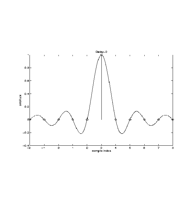
A delay filter is equivalent to an allpass filter(in the range -pi < w < pi) with a linear phase response, where the slope is an integer. For a slope of 3, we would get an impulse response as shown below.

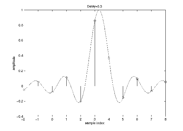
Note that this impulse response is finite in length--the only non-zero value is at n=3. Thus, this delay filter is easily implemented. However, to implement a delay of 3.3 samples, for instance, the ideal impulse response would be as follows

This impulse response is infinite in extent and non-causal so that it is impossible to implement in a real-time system [3]. Thus, real fractional delay systems can be at best approximations of the ideal impulse response just seen. There are many methods to go about this approximation; these are the methods discussed in [3]. There are both FIR and IIR implementations of the desired frequency and phase response.
An important consideration is the speed at which the coefficients for the FIR or IIR filter can be calculated, since the idea is to have a fractional delay that is adjustable in real-time. For IIR filters, only the subset of allpass filters is considered--namely those that have a magnitude response of 1 for all frequencies. This is a necessary constraint for obtaining a suitable IIR filter in a reasonable amount of time. As we learned in 431, [4] enumerates the comparisons between IIR and FIR--FIRs have better numerical properties while IIRs can be implemented using a lower order filter, which translates into computational speed.
Julius Smith sent us some code that incorporates fractional delay into a delay line: pluckfrac.c . We couldn't use this code directly because of the manner it receives input, but we did look at the fractional delay implementation it uses and attempted to use it in a modified version of pluck.cc. Looking at [4], we recognize his implementation as a first-order allpass/IIR Thiran filter. [4] states that the Thiran filter is characterized by a maximally flat group delay at the zero-frequency: we understand this to imply that the phase will remain rather linear for most of the frequency range.
A general allpass filter is given by the form

Thus the design task for an allpass filter is to find the coefficients a that best implement the desired linear phase response (or equivalently--flat group delay response, since the group delay is the derivative of the phase response). For the first-order Thiran approximation, the coefficient a1 is given by

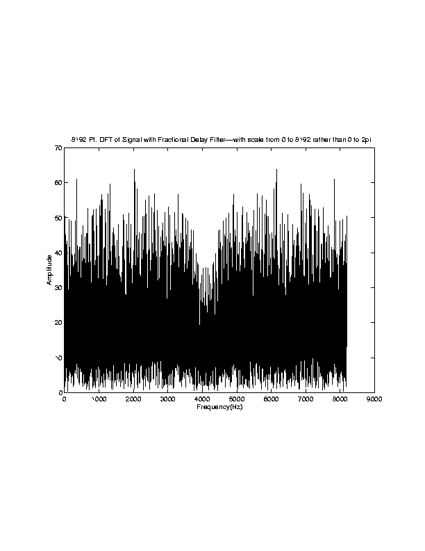
We tried to simply cascade this Thiran filter with the low-pass filter for attenuation, which is theoretically possible since both functions are implemented as LTI systems, which are commutable--[5] discusses using a fractional delay filter in series with the loop filter. The code in which we attempted this is given in pluck2.cc. The results were disastrous. The frequency content at the output of the "tuned" delay line, set to play at 440 Hz, was as shown below.

The amplitudes relative to the sample rate 8192 are small--so this frequency response corresponds to "grass"--a small freq. response relatively uniform across the spectrum. The result more or less sounded like white noise. Unable to figure out what went wrong, we emailed Julius Smith for advice, but he was out of town. If he posts a reply that could explain the problem--we will append that to this page so that a future group might possibly be able to use his fractional delay code.
A real physical model of an instrument contains terms higher than the second-order ones that comprise the wave equation. When these are added in, deispersion effects are seen; in other words, the velocity of a sine wave becomes frequency-different. It is derived in [2] that the relation of wave speed to discrete-time frequency is given by

This frequency-dependent velocity implies that each frequency component suffers a different phase shift during a single sampling period. To account for this effect, the basic idea is to replace each of the unit delay filters with a frequency-dependent delay filter that implements the appropriate delay (generally fractional) for each frequency[2]. However, the commutability of LTI systems can be utilized again, so that the dispersion filter can be consolidated. In [2], there is one dispersion filter for each rail. Any of a number of filter design techniques can be used to achieve the required phase response. It turns out that consolidating the filters typically causes a high-order filter to be needed (we find this unsurprising--in order for a filter to distinguish between many different frequencies in the time domain, there must be a significant number of delays in the filter).
We did not fully explore the filter design techniques, but [2] does give a good discussion of the group/phase delays that will be summarized here. The phase and group delays are equally valid means of specifying the phase response of a system--as good as the typical specification of phase versus frequency. The group delay is as defined in class, while the phase delay is defined as

A phase response specified in either way can be used as a basis for a filter design, so which specification method, phase delay or group delay, should one use? It depends on which of the two effects of dispersion one is more concerned with. Dispersion does 2 things: 1)it affects the tuning of the overtones and 2) it affects the decay time of different frequency components.
The first is related to the phase delay--different frequencies/overtones suffer different delays so that they all have different round-trip times through the delay line, which affects their tuning. Thus in order to optimize the tuning of the overtones, one should use a design method that optimizes phase delay rather than group delay.
The second effect of dispersion is related to the group delay; the group delay gives the effective delay seen by a group of frequencies around a central one. When attenuation is added, each overtone in the original spectrum becomes a group of frequencies spread around the overtone. Thus, the group delay function specifies the effective delay seen by each decaying group of frequencies (the fundamental group and the overtone groups). Different groups suffer different delay times. We (the gang) understand this to mean that a group which suffers a longer delay time will take longer to decay, because the longer delay implies a longer round-trip time through loop and, since the attenuation per round-trip is fixed, therefore a longer time to decay. The attenuation per round-trip is fixed by a^N where a is the frequency-dependent damping coefficient (determined by H(e^jw) of the attenuation filter) and N is the number of delay blocks in the line.
Thus, if one is mainly concerned with controlling the decay times of different frequency components in the signal, then one should choose a design method based on the group delay.
The filter design literature proved too daunting at the time of reading it, but having now gone through the filter design material in class, the literature seems more accessible. Unfortunately, there is not enough time to play with different dispersion filters.
[1] Smith, Julius O.. "Physical Modeling Using Digital Waveguides." Computer Music Journal, vol. 16, no. 4, pp. 74-91.
[2] Smith, Julius. O.. "Acoustic Modeling Using Digital Waveguides." In Musical Signal Processing, chapter 7, ed. Roads, Pope, Piccialli, and De Poli. Swets and Zietlinger: 1997.
[3] Smith, Julius. O.. "Physical Modeling Synthesis Update," Computer Music Journal, vol. 20., no. 2, 1996.
[3] Laakso, T., V. Valimaki, M. Karjalamen, and U.K. Laine. "Splitting the Unit Delay--Tools for Fractional Delay Filter Design" IEEE Signal Processing Magazine. January 1996.
[4] D.A. Jaffe and J.O. Smith. "Extensions of the Karplus-Strong Plucked String." Computer Music Journal, vol. 7, no. 2 , pp. 56-69. 1983.