Thoracic Cavity Phantom

To be able to simulate and test the performance of our back-projection
algorithm, we first needed to construction a thoracic (chest) phantom.
A phantom is a loose replica of the anatomical structures in the
human body as seen through a perpendicular slice. One of the more
popular models is the Shepp and Logan head phantom [7]. It contains
different ellipses and circles to define regions of varying density.
Our thoracic model is very similar to the Shepp-Logan model in the
sense that it also uses ellipses and circles to distinguish regions of different
densities. By using these geometries, the phantom is an analytic model. In other
words, the model will accept projections from any angle using any
arbitrary limit on the resolution. Models which are defined for
a preset resolution are limited to that specific sampling grid and a limited
subset.
Our basic model captures the three main anatomical structures: the lungs, heart,
and spinal column without the rib cage. As seen in Fig. 2.1, these elements
are clearly visible. Regions of like functional activity (e.g., right and left lung)
are assigned similar densities, although not exactly the same. Dislike
functional components have widely varying densities.
This is meant to test the resolution and range of the reconstruction algorithm.
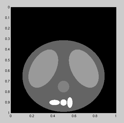
Figure 2.1 The basic thoracic cavity phantom used for the simulations.
The original image was 1000x1000 pixels. All images in
Section 2 are reduced in resolution to fit the page.
Our model also has the ability to grow specific regions asymmetrically, and
shift the entire structure horizontally. Region growth is reasonable given the expansion
and contraction of the heart, lungs, and chest wall. Horizontal
translation might occur in patients that are unable to have their
movements controlled (e.g., pediatric or epileptic patients). An example of
the horizontal movement is shown in Fig. 2.2.
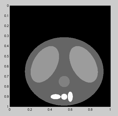
Figure 2.2 The basic thoracic cavity phantom shifted 0.04 to the left.
(Reduced from 1000x1000 pixels.)
Fig. 2.3 demonstrates the asymmetric growth of the lungs and chest wall, and the symmetric growth of the heart. The image shows the difference between
the original phantom (Fig. 2.1) and the phantom with all regions grown to their
maximum size.
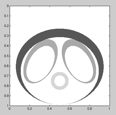
Figure 2.3 The difference between the basic thoracic cavity phantom
and the phantom with all regions at maximum growth.
(Reduced from 1000x1000 pixels.)
The model is composed of seven elliptic objects (a circle is a special case of an ellipse). All of the objects, even with maximum shift and growth, remain in a square bounded by the coordinates (0,0) and (1,1). Different densities are assigned to the interior of each ellipse, and are constant unless a boundary is crossed. Table 2.1 lists each object's parameters and assigned densities. All coordinates are referenced from the lower, left corner which is (0 , 0).
Three MATLAB programs compose the suite of tools for generating and viewing the phantom.
The heart of system is project.m. Project takes two pairs of x-axis
and y-axis coordinates and calculates the integral of the densities along that line. Regions
outside the body have zero density. The location of the coordinate pairs are arbitrary. They
can be inside the body, which would be useful for positron emission studies, and also outside
of the unit square.
Since project only works on one projection line at a time, arbitrary arrays of projections from any angle are possible. Parallel beam and fan beam projections [3-5] are just two examples of what can be calculated. Three other inputs are also required. The horizontal shift and the growth of the heart are needed. Also, independent of the heart, the growth of the lungs and chest wall are combined into the last parameter.
The two other programs in the suite are modgraph.m and projgraf.m. These algorithms allow the user to view the 2-D thoracic cavity phantom. Examples are shown in Figs. 2.1 and 2.2. Modgraph has the same geometries as project; however, due to rounding errors in MATLAB, low resolution images do not exactly correspond with the results from project. The value of modgraph is that it is fast in generating an image. Projgraf on the other hand is relatively slow, but it uses project to generate the image; therefore, it can be used to create an ideal image. The output from projgraf is used to compare against the reconstruction algorithm results. Please see the overview section under the MATLAB code, and the specific MATLAB files for further information.