COMP 310 |
Using the Green UML Plugin for Eclipse |
|
|
The open-source Green UML plug-in, from the Computer Science and Engineering Department at the University at Buffalo (State Univ. of New York), enables the developer to generate Java code by directly creating and manipulating a UML diagram. Likewise, a UML diagram can be created from existing code ("round-trip engineering"). Changes in the diagram are immediately reflected in the code and changes in the code are reflected in the diagram right away as well. This frees the developer to focus on the design and architecture of their system without worrying about the syntactical details of the programming language.
To install the Green UML plug-in, please go to the Eclipse installation page.
If you are new to UML class diagrams, it is highly recommended that you review the basics of UML first.
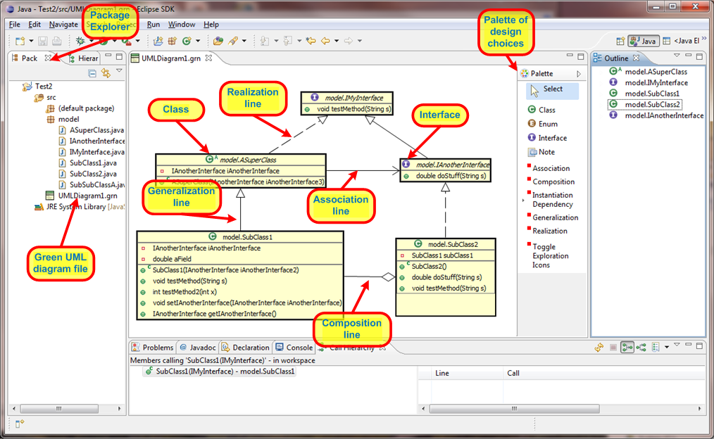
Green UML Screen Shot
Note: Sometimes a change made directly in the Java code does not immediately show up in the diagram. It is recommended that after making changes directly to the code, when switching back to the diagram, right-click in any clear area of the diagram and select "Refresh Editor". This will insure that the diagram is properly synchronized with the code.
Important Note: Green UML will not work with classes in the default package! In practice, this is not really a restriction because you should always put all of your classes in packages and never have code in the default package.
Create a New Blank Diagram
Create a New Diagram from an Existing Class or Interface -- creates a new class diagram with
Green UML will create an XXX.grn file in the root of the src folder (the default package location). To rename a class diagram, highlight it's *.grn file and go to the Eclipse main menu and select File/Rename or hit the F2 function key.
Create a New Class or Interface in the Diagram
Green UML will automatically generate the appropriate Java file for your new class or interface and will also auto-generate the code stubs for the class or interface.
Add an Existing Class or Interface to a Diagram
To add an existing class or interface to a diagram, be sure that the desired diagram is open and visible.
Adding a method or field:
Green UML will automatically generate a stub (signature but no code body) for any methods and fields that are made.
Editing an existing method
Generalization Lines (solid lines with closed arrowheads) indicate that a subclass extends superclass or an sub-interface extends a super-interface. The arrow will point from the subclass (sub-interface) to the superclass (super-interface).
Realization Lines (dotted lines with closed arrowheads) indicate that a class implements an interface. The arrow will point from the class to the interface.
Association lines (tailless solid lines with open arrowheads) indicate that one class holds a static reference to another class or instance of an interface, i.e. it has a field of the referenced type. The association line points from the class with the reference to the referenced class. Green UML has the erroneous notion unfortunately, that all such fields are initialized via constructor input parameters, so it auto-generates both the field and adds constructor code to initialize it via a constructor input parameter. Unfortunately, this constructor code will need to be deleted if one initializes the field in a different manner, such as by using a factory object.
Composition lines (solid lines with no arrowheads and a diamond-shaped tail) indicate that one class holds a static reference to another class or instance of an interface, i.e. it has a field of the referenced type, but also explicitly constructs the objects being referenced. Colloquially, we say that one object "owns" another. The composition line points from the "owner" to the referenced class. Green UML has the erroneous notion unfortunately, that all such fields are initialized via constructor input parameters, so it auto-generates both the field and adds constructor code to initialize it with the referenced class's constructor.. Unfortunately, this constructor code will need to be deleted if one initializes the field in a different manner, such as by using a factory object. Green UML is currently unable to handle an composition with an abstract class or interface, which is rather common.
Dependency lines (tailless dotted lines with open arrowheads) are used to indicate a variety of usually dynamic relationships between classes and interfaces, such as taking another class as an input or returning it from a method, or instantiating it for use as a local variable or value. If class "A" uses class "B", the dependency arrow will point from class "A" to class "B".
Green UML supports the two dependency scenarios. In the Palette, you may see either the "Instantiaton Dependency" or "Local Assignment Dependency" option. Clicking the small triangle next to the visible choice will show you the other choice. A "push-pin" icon lets you show both options at once.
Instantiation Dependency is when a method in one class instantiates another class for use as a value in a method.
Local Assignment Dependency is when a method in one class creates a local variable of the type of the target class of the dependency.
Notes are just boxes of text placed on the diagram to help the reader understand it better.
Green UML has a feature where it can automatically add the superclass or implemented interface of a selected class onto the diagram. This is referred to as "incremental exploring". If your diagram looks like the following, where an "ALL......" is displayed under the class name, the exploration feature is activated.
![]()
Clicking on the "ALL" will display the superclass or interface. You can choose what to show by right-clicking the class and selecting "Incrementally Explore".
Clicking the "Toggle Exploration Icons" option in the Paletter will turn the incremental exploration feature on and off.
Green UML incorrectly uses an empty diamond symbol to denote a composition--the UML standard is to use a filled diamond. Empty diamonds are generally used for "aggregations" which closely resembles Green UML's "associations", which is really the generic term encompassing both aggregations and compositions. See, for instance, http://cnx.org/content/m11658/latest/ and http://en.wikipedia.org/wiki/Class_diagram.
BUG in Green 3.5.0 when branching in SVN: In this version (and presumably, earlier versions as well) of Green UML, the .GRN diagram file holds hard-coded references to the Eclipse project folder. These references are NOT updated when the source code is branched and subsequently copied to another project folder. Thus, in the branched code, the diagrams will appear blank because Green UML cannot find the source files because it is looking in the wrong place. Work around: The .GRN diagram files are just ASCII text files in an XML-like format. Use any text editor, e.g. Notepad, to open the file and globally search and replace all occurances of the old project folder name with the new project folder name.
© 2017 by Stephen Wong