Main Page Explanation & FAQ Code Details Conclusions

Explanation and FAQ
The system buffers the output from each of the microphones and uses code similar to our fshift.m to find the delays between the desired pairs of microphones. The system then derives information about the sources's location based on these delays.

How do we find the shift?

First, we observe (based on the Cauchy-Schwarz Inequality) that the inner product between the 2

phase2a.jpg (14181 bytes)
Figure 1: 20 Sample Phase Shift between input signals.
signals is at a maximum when they are aligned. The naive way to implement this is to compute the inner product of the 2 signals for many different shifts. The shift that corresponds to the maximum inner product would be the phase delay between the 2 signals. However, with a little insight, it becomes clear that computing these inner products is equivalent to finding the linear convolution between one signal and the time inverse of the other. The next logical step is to compute this convolution in the frequency domain, to take advantage of the
O(nlogn) FFT algorithm. We can multiply the FFTs of the 2 signals (one signal time-inverted), and take the inverse FFT of the result.
One consideration that we must make however, is the fact that although we are processing the signals in blocks, they are actually infinite length (well, not really, but they are MUCH longer than the block size). It seems that what we would like to do is take the linear convolution of the entire signals. This is not desirable, nor achievable. In doing so, we would lose the ability to recognize the position of a signal if it changes over time.

Zero-padding both signals to change the discrete circular convolution to a linear


phase2a.jpg (14181 bytes)
Figure 2: Result of Fast Convolution: Peak Corresponds to 20 sample shift

convolution is not sufficient. Starting at a shift of 1, this method begins bringing zeroes into the inner product. This puts a triangular envelope on the result, causing the inner product for any shift to be smaller, depending on how much it is shifted. We want a uniform weighting for every shift, so we must pad one of the signals with MORE SIGNAL, and pad the other signals with zeroes. Effectively, we compare the center 1/2 of the bottom signal to the entire top signal. We can then shift by 1/4 the block size without bringing extra zeroes into the inner product. We can then simply throw away the "fringe" results that occur near the ends of the convolution, and only consider the valid part near the center. An example of code that finds the shift is given here: fshift.m

The selected block size affects many things, including the speed at which the system can run. It also determines how often we locate the signal, and thus determines our ability to track its motion. Also, the block size must be large enough to accurately determine shifts of the maximum possible extent. The restriction on the minimum block size is that it must be large enough to enable us to find a shift of (Radius of Array)*(sampling frequency)/(speed of sound) in either direction. (The required block size is roughly 4 times this figure.)

It is also desirable to filter out the high frequency content of these 2 signals, for reasons that will become apparent later.

We have the shift between 2 microphones. What can we do with it?

After some trigonometry and geometry, we can derive an equation of two variables (R and theta) that describes the possible location of the source.

Cos(theta) = (Alpha^2 - C^2 - 2*R*Alpha)/(-2*R*C)

where alpha is the distance sound travels in the given delay, and C is the distance between the microphones.

2micb.jpg (15171 bytes)
Figure 3: Output from 2-Microphone Array

The azimuth (direction) of the detected signal can be easily determined from the graph, and can be approximated as arccos(alpha/C). A function which computes the azimuth for two microphones is given here: 2micplot.m


We know the angle, how about range?

Ranging with two microphones is possible, but we must know use more than just the delay. We can range, assuming that the signals are propagating as spherical waves, using intensity difference between the 2 signals. This is possible with the assumption that the intensity decreases proportionally to the inverse square to the source. Unfortunately, this is very sensitive to noise. Also, sound isn't significantly attenuated in the typical microphone radius distance, which makes the intensity difference negligible.

Is there a better way to range?

There is a better way to range. If we use more than one pair of microphones, we can calculate two separate angles, and use them along with the base distance to triangulate the location of the signal source. An example of code to do this for an array of 4-microphones is here: quadmath.m The increase in the number of microphones and the addition of ranging increases the computation and the complexity of the equations. However, the increase in floating point operations is negligible compared to the number of operations performed to compute shifts.

What are the limitations of the 2-microphone system?

One limitation of using a 2-microphone system is an effect called "endfire." Endfire occurs along the axis joining the two microphones. Endfire is inherent in the geometry of two-element signal arrays that discretely sample signals. A difference of one sampled shift near the axis can be equal to several degrees of azimuth. Close to the perpendicular bisector of the array, the system becomes more resilient, and azimuth calculation is not impaired in an appreciable manner by small errors. Because endfire is an inherent quality of the array, there is no way of resolving this difficulty without adding more microphones. Here is an example of code that creates every possible source position

that the two microphone system can produce: endfire.m. It is generated by using every possible shift difference between the microphones for a given array radius.

There is also a tradeoff between frequency sensitivity and resolution. Because the system is sampling a signal in space, the highest frequency we can accurately resolve depends upon the array radius, the speed of sound in air, and the sampling frequency. The speed of sound in air is a constant that cannot be changed. However, the array radius can be altered to accurately resolve higher frequencies. Because higher frequencies imply shorter wavelengths,


phase2a.jpg (14181 bytes)
Figure 4: Endfire: Loss of resolution along axis of array

we can resolve higher and higher frequencies by placing the microphones closer together. However, the closer the microphones come together, the more difficult it becomes to resolve unique angles. Endfire becomes worse as the array radius becomes smaller. Therefore, the array radius must be large enough to maintain an acceptable resolution while being capable of processing an acceptable frequency band.

One thing that can be done is filtering out the high frequency content to accept any signal without having errors due to high frequencies. This is only possible if the signal also has enough low 
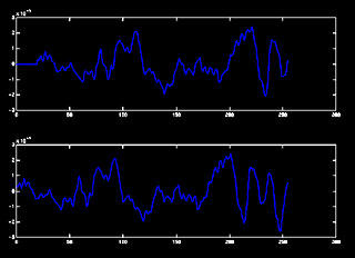
frequency content for us to find it's alignment. The entrance to Beethoven's Fifth Symphony contains significant low frequency content, which made it possible to use as a test signal.

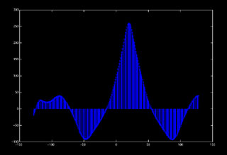
Why does this loss of resolution matter?

Loss of resolution is manifested as error in angle measurement. Worse, these small errors in angle result in large errors in range estimation. The very fact that the sample shifts are integers places a restriction on detectable range. For example, with an array radius of 1 meter (ridiculously large for air, but it shows that even accepting a bad frequency response doesn't help), a change of 1 sample at the edge of our detectable range moves the apparent location from approximately 70 meters to infinity.

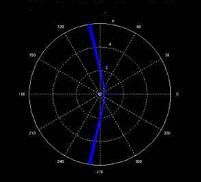
This effect is the reason why sonar-like systems typically fall into 2 types, Near-Field and Far-Field. Our system is a near field implementation, which allows the ability to range up to the previously described limit. If we decided to give up on ranging, we could have a far-field implementation. The far-field implementation depends on the simplifying assumption that the signal's angle of arrival to each of our microphones is the same. (Essentially assuming that the wave-front is a plane wave, rather than a spherical wave). Unfortunately, it seems that the only way to range in the far field is to increase the size of the array; which is the same as making the far-field part of the near-field.

Are the limitations of the 2-microphone system still present in a multiple microphone system?

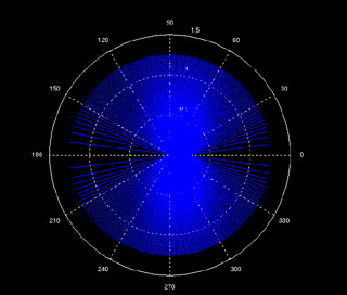
The limitations of the two microphone system are present to some extent in any system with more than 2 microphones. The loss of resolution due to endfire is reduced because we can always select and use pairs of microphones that have acceptable resolution in the direction of the signal source. The drawback to this is that we have to calculate the shifts for all of the pairs before we can know which ones to use. We are, in effect, throwing MFLOPS at the problem.

The frequency sensitivity restriction still exists, however, because we are still sampling only once every array radius. This particular problem is the primary reason why passive sonar-like systems are not used in air. A medium in which sound propagated more quickly, however, would have much larger wavelengths. In such a medium, a system such as ours would become workable. In other words, we have confirmed that it works best in the types of applications in which SONAR is typically used.


Main Page Explanation & FAQ Code Details Conclusions