|
|
|
Sensor DesignWithout sensors, a robot is just a machine. Robots need sensors to deduce what is happening in their world and to be able to react to changing situations. This chapter introduces a variety of robotic sensors and explains their electrical use and practical application. The sensor applications presented here are not meant to be exhaustive, but merely to suggest some of the possibilities. Please do not be limited by the ideas contained in this chapter! Assembly instructions for the kit sensors are given in Section 2.6. Sensors as TransducersThe basic function of an electronic sensor is to measure some feature of the world, such as light, sound, or pressure and convert that measurement into an electrical signal, usually a voltage or current. Typical sensors respond to stimuli by changing their resistance (photocells), changing their current flow (phototransistors), or changing their voltage output (the Sharp IR sensor). The electrical output of a given sensor can easily be converted into other electrical representations. Analog and Digital SensorsThere are two basic types of sensors: analog and digital. The two are quite different in function, in application, and in how they are used with the RoboBoard. An analog sensor produces a continuously varying output value over its range of measurement. For example, a particular photocell might have a resistance of 1kin bright light and a resistance of 300k in complete darkness. Any value between these two is possible depending on the particular light level present. Digital sensors, on the other hand, have only two states, often called "on" and "off." Perhaps the simplest example of a digital sensor is the touch switch. A typical touch switch is an open circuit (infinite resistance) when it is not pressed, and a short circuit (zero resistance) when it is depressed. Some sensors that produce a digital output are more complicated. These sensors produce pulse trains of transitions between the 0 volt state and the 5 volt state. With these types of sensors, the frequency characteristics or shape of this pulse train convey the sensor's measurement. An example of this type of sensor is the Sharp modulated infrared light detector. With this sensor, the actual element measuring light is an analog device, but signal-processing circuitry is integral to the sensor produces a digital output. Sensor Inputs on the RoboBoardThe RoboBoard contains input ports for both analog and digital sensors. While both types of ports are sensitive to voltage, each type interprets the input voltage differently and provides different data to the microprocessor. The analog ports measure the voltage and convert it to a number between 0 and 255, corresponding to input voltage levels between 0 and 5 Volts. The conversion scale is linear, so a voltage of 2.5 volts would generate an output value of 127 or 128. The digital ports, however, convert an input voltage to just two output values, Zero and One. If the voltage on a digital port is less than 2.5 Volts, the output will be 0, while if the input is greater than 2.5 Volts, the output will be 1. Thus, the conversion is very nonlinear. Reading Sensor InputsThe C library function analog(port-#) is used to return the value of a particular analog sensor port. For example, the IC statement
sets the value of the variable val equal to the output of port #27. Many devices used as digital sensors are wired to be active low, meaning that they generate 0 Volts when they are active (or true). The digital inputs on the RoboBoard have a pull-up resistor that makes the voltage input equal to 5 Volts when nothing is connected. A closed or depressed touch switch connected to a digital port would change that voltage to 0 Volts by shorting the input to ground. The resulting outputs: open switch , and closed switch , are the logical opposite of what we usually want. That is, we would prefer the output of the digital port to have value 0 or False normally, and change to 1 or True only when the switch hit something (like a wall or another robot) and was depressed. The IC library function digital(port-#), used to read a True-or-False value associated with a particular sensor port, performs this logical inversion of the signal measured on a digital port. Hence, the depressed touch switch (measuring 0 Volts on the hardware) causes the digital() function to return a 1 (logic true) or logical True value. For example, the C statement
returns a True value (the number 1) and calls the function do_it() if the value at port #2 was zero volts (indicating a depressed switch). Connector Plug Standard
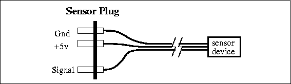
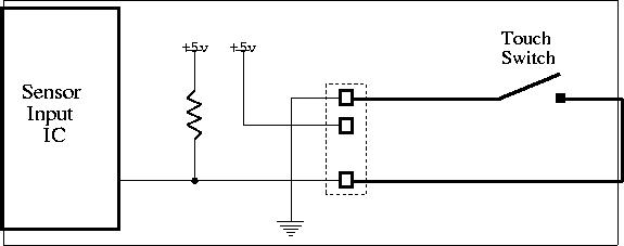
The standard plug configuration used to connect sensors to the RoboBoard is shown in Figure 9.1. Notice that the plug is asymmetric (made by removing one pin from a four-pin section of male header), and is therefore polarized. The plug can only be inserted in the RoboBoard port in one orientation, so once the plug is wired correctly, it cannot be inserted into a sensor port backwards. This makes the plug much easier to use correctly, but, of course, if you wire it incorrectly, you must re-wire it since you cannot turn the plug around. Generally the sensor is connected to the plug with three wires. Two of the wires supply 5 Volt power from the RoboBoard, labeled "+5v" and "Gnd." The third wire, labeled "Signal" is the voltage output of the sensor. It is the job of the sensor to use the power and ground connections (if necessary) and return its "answer", as a voltage, on the Signal wire. Sensor Wiring
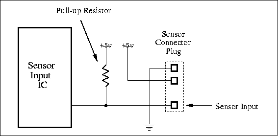
Figure 9.2 shows a diagram of circuitry associated with each sensor. This circuitry, residing on the RoboBoard, is replicated for each sensor input channel. The key thing to notice is the pull-up resistor wired from the sensor input signal lead to the 5 Volt power supply. There are two reasons why this resistor is used. First, it provides a default value for the sensor input -- a value when no sensor is plugged in. Many ICs, such as those on the board that read and interpret the sensor voltage, do not perform well when their inputs are left unconnected. With this circuit, when nothing is plugged into the sensor port the pull-up resistor provides a 5 Volt bias voltage on the sensor input line. Thus, the default output value of an analog port is 255, while the default output value of a digital port is 0 or logic False. (Remember that the 5 Volt default input value would lead to a digital value of 1 except that this value is inverted by the digital() library function, as explained earlier.) Second, the pull-up resistor is also used as part of the voltage divider circuit required for some of the analog sensors, as explained in Section 9.2.4. The resistors on the RoboBoard eliminate the need for an additional resistor on each of the sensors. The Voltage Divider Circuit
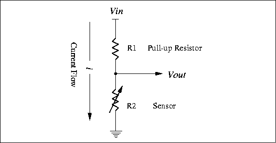
Most of the sensors used in the RoboBoard kit make use of the voltage divider circuit shown in Figure 9.3. In the voltage divider, the voltage measured at the common point of the two resistors,
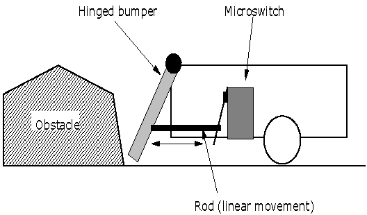
In ELEC 201 applications, has a fixed or constant value (as shown in Figure 9.2), while is the variable resistance produced by the sensor. is the positive voltage supply, fixed at 5 volts. Thus the signal can be directly computed from , the resistive sensor. From looking at the equation, it is easy to see that if is large with respect to , the output voltage will be large, and if is small with respect to , the output voltage will be small. The minimum and maximum possible voltage values are 0 and 5 Volts, matching the RoboBoard input circuitry range. Tactile SensorsThe primary sensors in the ELEC 201 kit used to detect tactile contact are simple push-button or lever-actuated switches. Microswitch is the brand name of a variety of switch that is so widely used that the brand name has become the generic term for this type of switch, which now manufactured by many companies. A microswitch is housed in a rectangular body and has a very small button (the "switch nub") which is the external switching point. A lever arm on the switch reduces the force needed to actuate the switch (see Figure 9.4). Microswitches are an especially good type of switch to use for making touch sensors.
Often, the switch is simply mounted on a robot so that when the robot runs into something, the switch is depressed, and the microprocessor can detect that the robot has made contact with some object and take appropriate action. However, creative mechanical design of the bumper-switch mechanism is required so that contact with various objects (a wall, a robot, etc.) over a range of angles will be consistently detected. A very sensitive touch bumper can be made by connecting a mechanism as an extension of the microswitch's lever arm, as illustrated in Figure 9.5.
Limit SwitchTouch sensors can also serve as limit switches to determine when some movable part of the robot has reached the desired position. For example, if a robot arm is driven by a motor, perhaps using a gear rack, touch switches could detect when the arm reached the limit of travel on the rack in each direction. Switch CircuitryFigure 9.6 shows how a switch is wired to a sensor input port. When the switch is open (as it is shown in the diagram), the sensor input is connected to the 5 Volt supply by the pull-up resistor. When the switch is closed, the input is connected directly to ground, generating a 0 Volt signal (and causing current to flow through the resistor and switch).
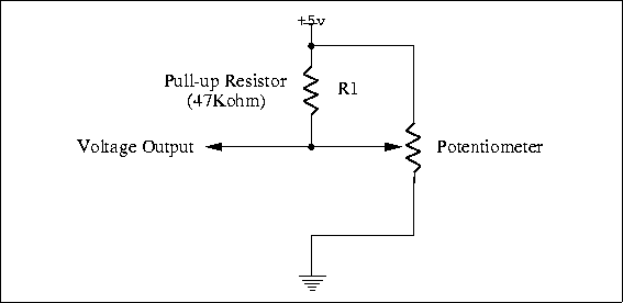
Most push-button-style switches are "normally open," meaning that the switch contacts are in the open-circuit position when the switch has not been pressed. Microswitches often have both normally open and normally closed contacts along with a common contact. When wiring a microswitch, it is customary to use the normally open contacts. Also, this configuration is the active-low mode expected by the standard library software used to read the output values from digital sensor ports. However, you can wire the switch differently to perform some special function. In particular, several switches can be wired in series or parallel and connected to a single digital input port. For example, a touch bumper might have two switches, and the robot only needs to know if either of them (#1 OR #2) are closed. It takes less code and less time to check just one digital port and to use parallel switch wiring to implement the logic OR function in hardware. Mercury Tilt SwitchAs the name suggests, a mercury tilt switch contains a small amount of mercury inside a glass bulb. The operation of the switch is based on the unique properties of mercury: it is both a conductor and a liquid. When the switch tilts mercury flows to the bottom of the bulb closing the circuit between two metal pins. ApplicationsThe mercury tilt switch can be used in any application to sense inclination. For example, the tilt switch could be used to adjust the position of an arm or ramp. Most thermostats contain a mercury tilt switch mounted on a temperature sensitive spring. Changes in temperature tilt the switch, turning the furnace or air conditioner on or off. PotentiometerA potentiometer (or "pot," for short) is a manually-adjustable, variable resistor. It is commonly used for volume and tone controls in stereo equipment. On the RoboBoard a 10k pot is used as a contrast dial for the LCD screen, and the RoboKnob of the board is also a potentiometer. In robotics, a potentiometer can be used as a position sensor. A rotary potentiometer (the most common type) can be used to measure the rotation of a shaft. Gears can be used to connect the rotation of the shaft being measured to the potentiometer shaft. It is easiest to use if the shaft being measured does not need to rotate continuously (like the second hand on a clock), but rather rotates back and forth (like the pendulum on a grandfather clock). Most potentiometers rotate only about 270 degrees; some can be rotated continuously, but the values are the same on each rotation. By using a gear ratio other than 1:1, the position of a shaft that rotates more than 270 degrees can be measured. A potentiometer connected to a shaft and a lever can also be used to determine the distance to a wall and to make the robot follow a path parallel to the wall. The lever, perhaps with a small wheel on the end, would extend from the side of the robot and contact the wall; a rubber band would provide a restoring force. If the robot moved closer to the wall, the lever would pivot, turning the shaft and the potentiometer. The control program would read the resulting voltage and adjust the robot steering to keep the voltage constant. Electrical DataPotentiometers have three terminals. The outer two terminals are connected to a resistor and the resistance between them is constant (the value of the potentiometer). The center terminal is connected to a contact that slides along the resistance element as the shaft is turned, so the resistance between it and either of the other terminals varies (one increases while the other decreases).
The assembly instructions suggest wiring the potentiometer in the voltage divider configuration, with the on-board pull-up resistor in parallel with one of the potentiometer's two effective resistances (Figure 9.7). This will yield readings of greater precision (although they will not be linear) than if the pot were used as a two-terminal variable resistor. You may want to try different circuits to determine which works best for your application. Light SensorsMeasurement of light provides very valuable information about the environment. Often, particular features of the game board (such as goals) are marked by a strong light beacon. The board surface has contrasting lines that can be detected by the difference in the amount of light they reflect. A variety of light sensors are provided in the ELEC 201 kit:
PhotocellPhotocells are made from a compound called cadmium sulfide (CdS) that changes in resistance when exposed to varying degrees of light. Cadmium sulfide photocells are most sensitive to visible red light, with some sensitivity to other wavelengths. Photocells have a relatively slow response to changes in light. The characteristic blinking of overhead fluorescent lamps, which turn on and off at the 60 Hertz line frequency, is not detected by photocells. This is in contrast to phototransistors, which have frequency responses easily reaching above 10,000 Hertz and more. Therefore, if both sensors were used to measure the same fluorescent lamp, the photocell would show the light to be always on and the photo-transistor would show the light to be blinking on and off. ApplicationsPhotocells are commonly used to detect the incandescent lamp that acts as a contest start indicator. They are also used to find the light beacons marking certain parts of the board, such as the goals. While they can be used to measure the reflectivity of the game board surface if coupled with a light source such as a red LED or an incandescent lamp, the IR reflectance sensors are usually better at this function. Photocells are sensitive to ambient lighting and usually need to be shielded. Certain parts of the game board might be marked with polarized light sources. An array of photocells with polarizing filters at different orientations could be used to detect the polarization angle of polarized light and locate those board features. Electrical DataThe photocell acts as resistor in the voltage divider configuration discussed in Section 9.2.4. The resistance of a photocell decreases with an increase in illumination (an inverse relationship). Because of the wiring of the voltage divider (the photocell is on the lower side of the voltage divider), an increase in light will correspond to a decrease in sensor voltage and a lower analog value. Infrared Reflectance SensorThe infrared reflectance sensor is a small rectangular device that contains a phototransistor (sensitive to infrared light) and an infrared emitter. The amount of light reflected from the emitter into the phototransistor yields a measurement of a surface's reflectance, for example, to determine whether the surface is black or white. The phototransistor has peak sensitivity at the wavelength of the emitter (a near-visible infrared), but is also sensitive to visible light and infrared light emitted by visible light sources. For this reason, the device should be shielded from ambient lighting as much as possible in order to obtain reliable results. ApplicationsThe amount of light reflected from the emitter into the phototransistor yields a measurement of a surface's reflectance (when other factors, such as the distance from the sensor to the surface, are held constant). The reflectance sensor can also be used to measure distance, provided that the surface reflectance is constant. A reflectance sensor can be used to detect features drawn on a surface or segments on a wheel used to encode rotations of a shaft. It is important to remember that the reflectivity measurement indicates the surface's reflectivity at a particular wavelength of light (the near-visible infrared). A surface's properties with respect to visible light may or may not be indicators of infrared light reflectance. In general, though, surfaces that absorb visible light (making them appear dark to the eye) will absorb infrared light as well. The sensor part (the phototransistor) can be used alone as a light sensor, for example to detect the starting light, and it is usually much more sensitive than the photocell. Electrical Data
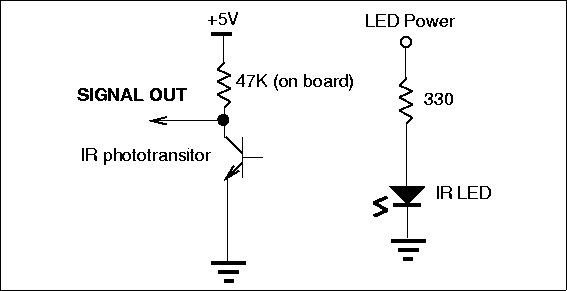
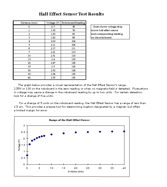
PhototransistorThe light falling on a phototransistor creates charge carriers in the base region of a transistor, effectively providing base current. The intensity of the light determines the effective base drive and thus the conductivity of the transistor. Greater amounts of light cause greater currents to flow through the collector-emitter leads. Because a transistor is an active element having current gain, the phototransistor is more sensitive than a simple photoresistor. However, the increased sensitivity comes at the price of reduced dynamic range. Dynamic range is the difference between the lowest and highest levels that can be measured. The RoboBoard analog sensor inputs have a range of 0-5 Volts, and relatively small variations in light can cause the phototransistor output to change through this range. The exact range depends on the circuit used. As shown in Figure 9.8, the phototransistor is wired in a configuration similar to the voltage divider. The variable current traveling through the resistor causes a voltage drop in the pull-up resistor. This voltage is measured as the output of the device. Infrared EmitterThe light emitting element (an LED) uses a resistor to limit the current that can flow through the device to the proper value of about 10 milliamps. Normally the emitter is always on, but it could be wired to one of the LED output ports if you wanted to control it separately. In this way you could use the same sensor to detect the starting light (using the phototransistor with the emitter off) and then to follow a line on the board (normal operation with the emitter on). Infrared Slotted Optical SwitchThe infrared slotted optical switch is similar to the infrared reflectance sensor except that the emitter is pointed directly at the phototransistor across a small gap. As the name implies, the slotted optical switch is a digital sensor, designed to provide only two output states. The output of the switch changes if something opaque enters the gap and blocks the light path. The slotted optical switch is commonly used to build shaft encoders, which count the revolution of a shaft. A gear or other type of wheel with with holes or slots is placed in the gap between the emitter and detector. The light pulses created by the turning wheel can be detected and counted with special software to yield rotation or distance data. This detector also might be used to detect when an arm or other part of the robot has reached a particular position by attaching a piece of cardboard to the arm so that it entered the gap at the desired arm position. Electrical DataThe slotted optical switch operates in the same fashion as the infrared reflectance sensor, with the exception that a different value of pull-up resistor must be added externally for the particular model of optical switch we use. Modulated Infrared Light DetectorThe modulated infrared light detector is a device that combines an infrared phototransistor with specialized signal processing circuitry to detect only light that is pulsing at a particular rate. The ELEC 201 kit includes the Sharp GP1U52 sensor, which detects the presence of infrared light modulated (pulsed) at 40,000 Hz. Normal room light, which is not modulated, does not effect the sensor, a big advantage. This type of sensor is used for the remote control function on televisions, VCRs, etc. In ELEC 201 this sensor is used to detect the specially modulated infrared light emitted by the beacon on the opponent robot. The software can distinguish different pulse patterns in order to distinguish between the beacons on the two robots. (In a television remote, different pulse patterns would correspond to different functions, such a changing the channel up or down.) The principles of operation and use are explained further in Section 5.8, which also discusses the circuit used to create the modulated infrared light for the beacon. An explanation of the software interface to the Sharp sensors is given in Section 10.11.2. Other SensorsMagnetic Field SensorsThe ELEC 201 kit contains both an analog sensor that provides information about the strength of the magnetic field and a digital sensor, a magnetic switch. A device called a Hall effect sensor can be used to detect the presence and strength of magnetic fields. The Hall effect sensors have an output voltage even when no magnetic field is present, and the output changes when a magnetic field is present, the direction of change depending on the polarity of the field. The digital magnetic sensors are simple switches that are open or closed. Internally the switches have an arm made of magnetic material that is attracted to a magnet and moves to short out the switch contacts. These switches are commonly used as door and window position sensors in home security systems. The switch will close when it comes within 1'' of its companion magnet. ApplicationEither sensor can be used to detect magnets or magnetic strips that may be present on the ELEC 201 game board table. With the magnets typically used on the game board, the Hall effect sensor output voltage changes only a small amount when a field is present. The no-field voltage varies between sensors, but it is very stable for a particular sensor, so the small changes can be detected reliably to determine the presence of a magnet. Hall effect sensors can be used to make magnetic shaft encoders, by mounting a small piece of magnet on a wheel that rotates past the sensor element. Hall effect sensors can also be used to build a proximity sensor or bounce-free switch, which detects a magnet mounted on a moving component when it is near the sensor element. Magnetic switches are used in much the same way as a touch switch, except the switch closes when it is near a magnetic, instead of when it contacts something. The digital nature of the switch makes it easier to use than the Hall effect sensors, but it may be less sensitive. You should try both. They can also be used to make an inclination sensor by dangling a magnet above the sensor. Electrical DataThe Hall effect sensor included in the ELEC 201 kit is a digital device that operates from a 5 volts power supply. It uses about 6 mA of current for standard operation. It can sink 250 mA of current into its output, creating a logic low. The sensor cannot drive a logic high and therefore requires a pullup resistor for proper operation. Motor Current SensorThe motor output drivers of the ELEC 201 RoboBoard contains circuitry that produces an output voltage related to the amount of current being used by a motor. Since the motor current corresponds to the load on the motor, this signal can be used to determine if the motor is stalled and the robot is stuck. The voltage signal depends on a number of factors, including battery voltage, and must be calibrated for each application. This application is explained further in Section 5.4.1.
|